Astro U148
About
This connector can be used with the following devices: Astro U144, U148, and U149. It allows you to gather and view information from these devices as well as configure them.
This connector uses HTTP to monitor the device. It also uses an SNMP interface to receive traps from the device.
Configuration
Connections
This connector uses two interfaces: an HTTP interface to retrieve the data and an SNMP interface to collect the traps.
Depending on the setup, the HTTP configuration can be different: this connector can communicate directly with the U144/148/149 device being used, but it can also be configured to send the requests to the Astro U100 Controller, which will then serve as a proxy.
In either case, the SNMP interface collects the traps emitted by the device, so the SNMP IP address must be the IP address of the U144/148/149 device (not the controller).
HTTP Connection for Communication with U100C as Proxy
- IP address/host: The IP address of the Astro U100 Controller.
- IP port: The port of the destination, e.g., 80.
- Bus address: The IP address of the U148. In addition, "ByPassProxy" must be filled in to bypass any possible proxy that could block the HTTP communication. The two values must be separated by a semicolon, e.g., ByPassProxy;10.11.12.13.
HTTP Connection for Direct Communication
- IP address/host: The IP address of the U148.
- IP port: The port of the destination, e.g., 80.
- Bus address: This field can be used to bypass the proxy. To do so, fill in the value ByPassProxy.
SNMP Connection
- IP Address/host: The polling IP of the U148, e.g., 10.11.12.13.
- Port number: The port of the connected device, by default 161.
- Get community string: The community string in order to read from the device. The default value is public.
- Set community string: The community string in order to set to the device. The default value is private.
Credentials
When a new element is created, if the communication settings are OK, information can be polled from the device without authentication. However, to perform sets on the device, the Username and Password credentials need to be configured on the Login page.
The default credentials are:
- Username: admin
- Password: astro
Alarm forwarding
From version 1.0.0.20 onwards, you can enable/disable the Controller Alarm Forward parameter on the General page. This parameter enables or disables alarm forwarding to the Astro U100 Controller. If you want to forward alarms to the controller, the name of the controller element must have the format 'Controller Name'.'Name'.
How to Use
General
This page displays general information about the device. Some important parameters are available at the end of the first column:
Controller Name: This parameter shows the name of the Astro Virtual Controller element that manages this device. If no such element is used, the parameter will show the exception value N/A.
Communication Type:
- Direct Communication: The element sends the requests directly to the Astro module.
- U100C Proxy: The element sends the requests to the Astro U100 Controller, which will forward them to the Astro module. The controller acts as a proxy.
Connection Method: This parameter is only available in Direct Communication mode.
- Login: The element logs in to the device before every request (read and write requests).
- Anonymous: The element only logs in to the device for write requests. It does not log in for read requests.
Status
This page displays the status of the device, e.g., Temperature, Power Supply, CPU Load, etc.
Main
On this page, you can access the main configuration of the device, e.g., DNS, Time Source, Interfaces, etc.
Input Settings
On this page, you can configure the settings for the four F sockets. Each socket listens to a specific satellite.
The Satellites page button displays a list of all the detected satellites.
Transponder
This page contains two tables, the first containing the configuration settings of each of the transponders, and the second containing information on the current transponder status.
IP TX Settings
On this page, you can configure the output IP settings. The device contains 8 output IP channels. Each output IP is redundant (Data A and Data B).
CAM MUX
The CAM MUX is only functional for the U144 device. It enables the routing of the input satellite channel to a TX MUX input, using a matrix parameter. The same input can be connected to multiple outputs.
MUX
To adjust the setup of the multiplexers, the MUX Setup table can be used. This page displays an overview of the services that are currently assigned to the transport stream.
The Service Selection table will show the services that are currently assigned to a MUX.
Assigning a Service to a MUX
Click the Add Service page button at the bottom of the page.
A new window will open where you can configure your service.
Select a multiplexer, select a service, and select the required SID Out State.
Once all fields are filled in, click the Add Service button.
Fields like SID and SID Out will be filled in automatically in some situations. When the service is successfully assigned to a MUX, a new entry (with the newly assigned service) will be added to the Service Selection table. Note that it is important that you select a valid service for the multiplexer.
Removing a Service from the Transport Stream
To remove a service from the transport stream, click the corresponding Delete button in the Action column of the Service Selection table.
Modifying a Service
It is not possible to modify a service directly in the Service Selection table. Instead, you will need to remove the entry (with the Delete button in the Action column) and add a new one (see Assigning a Service to a MUX).
TX MUX
On this page, you can route the input satellite channel to an output IP channel, using a matrix parameter on the U148/149 device. The same input can be connected to multiple outputs. On the U144, the first 4 TX MUX inputs connect to the 4 CAM modules, while the other 4 directly connect to the 4 RF inputs.
Update/Config
On this page, you can upload/download config files to/from the device and perform a software update.
Downloading a file
In the list of files on the Update/Config page, click Download.
The following pop-up window will be displayed:
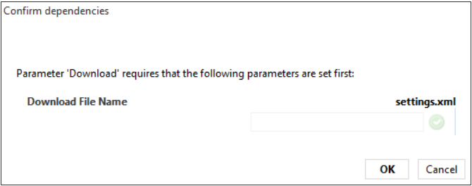
Enter the name of the file and click OK.
The file will be saved in the following location:
C:\Skyline DataMiner\Documents\<protocol name>\<element name>\<file name>
Uploading a file
Make sure the file you want to upload is placed in the following location:
C:\Skyline DataMiner\Documents\<protocol name>\<element name>\<file name>In the list of files on the Update/Config page, click Upload.
The following pop-up window will be displayed:

Configure the following parameters and click OK:
Module Name: Select the relevant Astro element in the system.
Upload File Name: Select the file from the list of files included in the folder mentioned earlier. If the file is not shown, use the Refresh File List button.
Performing a Software Update
The connector allows you to upload a firmware archive from the local disk of the DMA:
Make sure the archive is located in the following directory of the DMA: C:\Skyline DataMiner\Documents\Protocol Name>.
In the Firmware File dropdown box, select the file to upload.
If the file you want is not shown yet, click Refresh File List.
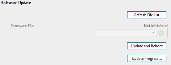
Click Update and Reboot to start the upgrade.
To follow the update progress, click the Update Progress page button. However, traps must be configured for this to be possible.
Licensing
This page shows the available licenses for this Astro device.
System Log
This page contains a table listing all the log entries. You can download the log files by clicking the Download buttons. To access the log settings, click the System Log Config page button.
Alarm Severities
On this page, you can set the severity for each alarm type.
Active Alarms
This page displays a table with the current alarms on the device.
Network
This page displays network parameters.
Note that these parameters are retrieved via SNMP. The polling can be enabled/disabled using the Network Data Polling toggle button.
Web Interface
This page displays the web interface of the device. Note that the client machine has to be able to access the device, as otherwise it will not be possible to open the web interface.
DataMiner Connectivity Framework
DCF is supported in range 1.0.0.x, from version 1.0.0.8 onwards.
Interfaces
Dynamic Interfaces
- Sat/RF Inputs (type: in) interfaces, created from the Input Settings table on the Input Settings page of the connector.
- Data Ethernet Outputs (type: out) interfaces, created from the Interface Configuration table on the Main page of the connector.
Connections
Internal Connections
Internal Connections between the Sat/RF Input Ports and the Ethernet Data Outputs are mapped and characterized by the following connection properties: Transponder Name, TS-ID, ONID, Input Frequency, and MC (Syntax "TX Destination IP:TX Destination Port" ).
Notes
We recommend creating Astro U148 elements on a DMA running the Windows Server 2012 R2 Standard operating system or higher. Elements that were created on a DMA running the Windows Server 2008 R2 Standard operating system can behave incorrectly. When multiple modifications are made to the settings.xml file in a short time period, only the first modification will succeed and the others will fail.