Cisco D9854
The CISCO D9854 advanced program receiver is designed for satellite content distribution applications requiring DVB-S and DVB-S2 reception capabilities with advanced digital outputs for digital-tier program distribution.
The connector uses SNMP to retrieve data from the CISCO D9854. The connector also allows you to configure certain parameters.
About
Version Info
| Range | Key Features | Based on | System Impact |
|---|---|---|---|
| 1.0.0.x [SLC Main] | Initial version. | - | - |
Product Info
| Range | Supported Firmware |
|---|---|
| 1.0.0.x | - |
System Info
| Range | DCF Integration | Cassandra Compliant | Linked Components | Exported Components |
|---|---|---|---|---|
| 1.0.0.x | Yes | No | - | - |
Configuration
Connections
SNMP Main Connection
This connector uses a Simple Network Management Protocol (SNMP) connection and requires the following input during element creation:
SNMP CONNECTION:
- IP address/host: The polling IP or URL of the destination.
- IP port: The IP port of the destination.
SNMP Settings:
- Get community string: The community string used when reading values from the device (default: public).
- Set community string: The community string used when setting values on the device (default: private).
Web Interface
The web interface is only accessible when the client machine has network access to the product.
How to use
You can find more information on the different data pages of the element below.
General
This page contains the description parameters for this receiver, along with the Logs and FTP configuration.
Ethernet
This page contains the Ethernet Setup table, where it is possible to configure the IPV4 Address, Mask and Gateway.
Input
On this page, you can configure the current input port (RF1, RF2, RF3, RF4, or ASI). For each RF, you can configure the Local Oscillators, Cross Over, Orbital Position, Polarization, and East/West Flag.
Demodulator
This page displays information such as Rx Modulation, Rx Downlink Frequency, Rx L-Band Frequency, and Rx LDP CBER.
Muting Thresholds
On this page, you can configure the muting thresholds for the DVBS and DVBS2 Transport.
Audio-Video
This page provides information related to the Audio and Videos Status. In addition to the Audio Service, several settings related to the video can be configured, such as the Video Output, Stream Aspect Ratio, and Aspect Ratio Selection.
Services
This page contains two tables, Channel Information and Decoded Program PIDs. The Caption and Subtitles can also be configured here.
PSI
This page contains the PSI Frequency table, which lists the available frequency plans stored in the receiver.
The PSI Tables and PSI Channels tables are also available on this page. However, note that the information in these tables is read-only.
Output
This page displays information related to ASI and MOIP. The Output Rate and Null Rate are also displayed for every output.
DPM Global
On this page, you can among others configure the ASI Output and MOIP Output Remapping Mode, Duplication Method, and Service ID Output.
DPM Details
This page contains the DPM Program Entry Configuration table. For every DPM Channel, the corresponding Output Channel and Action (Drop, Pass, or Map) can be configured.
DPM ASI Options
On this page, you can select the tables that will be passed, dropped, regenerated, or passed with rate control (PwRC) from the ASI.
DPM MOIP Options
On this page, you can select the tables that will be passed, dropped, regenerated, or passed with rate control (PwRC) from the MOIP.
Alarms
On this page, you can configure the different alarms available on the device. The page also displays the Active Fault List table.
IP Input
On this page, you can configure the IP Input Dejitter Algorithm, Flow FEC Mode, and Redundancy Mode
DataMiner Connectivity Framework
The 1.0.0.x connector range of the Cisco D9854 connector supports the usage of DCF.
DCF can also be implemented through the DataMiner DCF user interface and through DataMiner third-party connectors (for instance a manager).
Interfaces
Physical dynamic interfaces:
- Input: created for parameter table PID 350 type in.
- Output: created for parameter table PID 1200 type out.
Notes
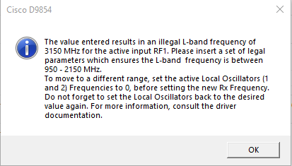
When you set the demodulator Rx Frequency (on the Demodulator page) and the active Local Oscillator inputs (on the Inputs page), the absolute difference (|Rx Frequency - LO|) of both must result in a L-band frequency between 950 and 2150 Mhz. If the difference is not within the mentioned range, a message will be displayed (see image below) and the previous value will be used instead.
If you want to change the value of both Rx Frequency and Local Oscillator, you can do so as follows:
Set the active Local Oscillator to 0.
Set the Rx Frequency to the desired value.
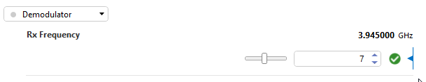
Set the active Local Oscillator to the desired value.
In case both Local Oscillator 1 and 2 are in use, you need to set both to 0. Note also that the procedure above only applies when you want to change both values while keeping a valid range, e.g., changing RX Frequency from 3 GHz to 7 GHz while also changing the Local Oscillator from 5 GHz to 8 GHz.
You can also configure an alternative RF Input to the desired values and then switch the active input over to the new configuration, as depicted below.
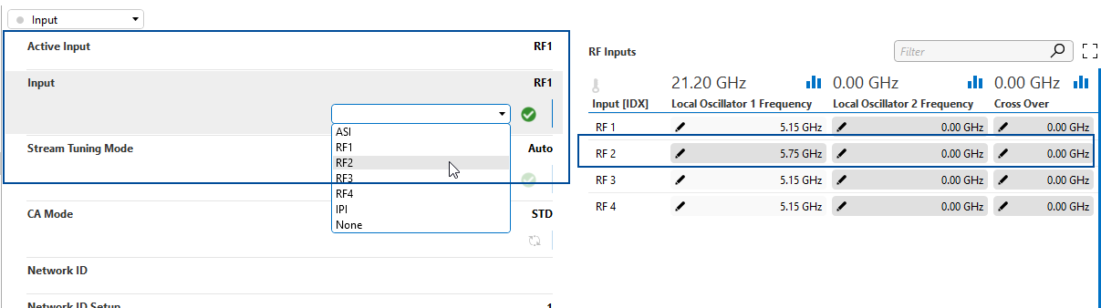
When you select a different RF Input and the new L-band is out of the mentioned range, an information message will be displayed similar to the one displayed above. However, the value will be set even though the resulting L-band will be invalid. It is then up to you to properly define this.