CISCO DCM
This connector can be used to monitor devices in the CISCO DCM D9900 series, such as the D9900, D9901 and the D9902. The connector also supports collaboration with the CISCO DCM Statmux D9036 (for which a dedicated connector is also available).
About
This connector polls some basic information, such as available boards, ports, and transport streams. Many other settings can also be monitored and displayed in a tree view, but these must be enabled before they will be polled. These other settings include: PIDs, Bitrates, CAM cards, FEC settings, etc.
Before using this connector, make sure you have read and understand the following sections of this Help: "Installation and configuration" and "Poll Manager".
Please note the following:
This connector was developed for DataMiner Cube, so it may not function correctly if you use the legacy application Element Display instead.
Firmware upgrades are usually backwards compatible, so there are generally no problems upgrading to most of the more recent versions. See "Supported Firmware Versions" section below.
Version Info
| Range | Description | DCF Integration | Cassandra Compliant |
|---|---|---|---|
| 1.0.0.x | Initial version, based on "SA DCM 2.0.0.36" connector. | Yes | Yes |
| 1.0.1.x | Added partial tables. | Yes | Yes |
| 1.0.2.x | Based on 1.0.0.104, but with partial tables. | Yes | Yes |
| 1.0.3.x [SLC Main] | SRM compatible. Major change because of display key change. Based on 1.0.0.107. | Yes | Yes |
Note
If you are using a version in the 1.0.3.x range prior to 1.0.3.93, a memory leak can occur when incorrect IIOP credentials are configured on the element. Make sure to upgrade to the latest version of this connector to prevent this.
Product Info
| Range | Supported Firmware |
|---|---|
| 1.0.0.x 1.0.2.x 1.0.3.x | Supported firmware depends on each command. To check the minimum version necessary to run a command, refer to the Minimum Required FW column on the Manager page. If this column has the value "any", there is no information in the document "DCM_IDL.pdf" about the minimum version to run that command, so it is assumed to be compatible with all firmware versions. For example, Command Get Boards requires firmware 6.9 or later.  |
Configuration
Prerequisites
The connector requires that Visual C++ 2008 (or 2010) Redistributional is installed. To verify this, go to: Control Panel > Programs and Features.
If this program has not been installed yet, you can download and install it from the following website: http://www.microsoft.com/en-us/download/details.aspx?id=29.
Installing the Connector
For connector versions up to 1.0.0.26
Unlike most connectors, the CISCO DCM connector is not just a plain XML protocol file. It is instead delivered as a ".DMUpgrade" package. This is because the connector requires additional DLLs that cannot be installed using a default .dmprotocol package.
To install the package:
Copy the upgrade package to one of the DMAs and double-click it. This will start the upgrade procedure.
Do not change any of the default settings.
Upload the connector or, if available, install the connector package. All required files should now be installed and ready for use.
Note: The DMUpgrade package does not install the XML protocol itself, but only the extra DLLs.
For connector version 1.0.0.27 and higher
From version 1.0.0.27 onwards, assemblies are supported in connector packages. Internally, the packages can be built using the connector tool page, if a package is not found for this version on the distribution platform. In case the Protocol Update Center does not support the version with DLLs yet, use a .dmprotocol package, or request one from your Technical Account Manager.
Creating an Element
The procedure below describes how you can set up your first element. To create further elements, the same steps can be used, though some of the steps can be omitted.
In DataMiner Cube, right-click in the Surveyor and select New > Element.
Specify a unique name for the element.
Optionally, add a description.
Optionally, assign an alarm template and/or a trend template.
Specify the main IP address.
Note
Double-polling one DCM on the same DMA is not possible.
More TCP/IP settings: specify the port. (Default: 161 -> used to receive SNMP traps).
Click Create to finish element creation.
Note
In versions before 1.0.0.14, the default port is 5003, but this setting is ignored by the connector. 5003 is the port used for IIOP communication, which is the main communication protocol used to poll the device. However, this setting has always been ignored by the connector and instead the port can be changed inside the connector (though this is not likely to be necessary). When you update a pre-14 version to version 14 or later, the port settings must be updated; otherwise the SNMP traps will not be received by the connector.
If communication does not work once the element has been created, follow the steps below to get the connection running. For any of the steps after the initial connection test, always perform this first test again to see if the connection works before moving to the next step.
Note that the first time an element is created using a connector on a DMA, it can take a few minutes before all the QActions are compiled. As such, it is advisable to wait at least one minute before you conclude that no data is available.
Connection Test
To test the connection:
Restart the element
Open the element card
Check on the Overview page if there are icons in the tree view.
If yes -> Test succeeded.
If no -> Test failed.
If the test failed, continue with the next step.
Verify IP Address
To verify the IP address:
Go to the Driver Settings page and check if the Management IP Address 1 is correct.
Verify if the Port parameters are set to 5003.
Optionally, supply the IP address of the second management port. A DCM usually has two management ports, located next to the power supply.
Note: The first IP address is not configurable in Data Display. To change it, right-click the element in the Surveyor, select Edit, and then define a new IP address in the element editor.
Test the connection again before you continue.
Verify IIOP Credentials
To verify the IIOP credentials:
Go to the webpage of the DCM device and log on as Administrator.
Open the page Security and select the tab OS Accounts. A list should appear with available OS accounts.
Make a new user account or edit an existing one. It is advisable to use the username guest and password guest and to make sure the option IIOP is enabled.
Go to the element card and open the IIOP page. You can find this page by clicking the corresponding page button on the Driver Settings page.
If you have an OS account with the username and password guest, you can set the IIOP Use Credentials to No; otherwise set this parameter to Yes and fill in the username and password.
Note:
- Keep in mind that the password is sent to the DCM in plain text, so a simple Wireshark capture can easily reveal the password (by filtering on IP and port 5003 and searching for logon).
- Up to version 1.0.0.87, the username and password must be the same for all elements on the same DMA. This constraint was removed in that version, so from that version onwards, each element can have its own credentials.
Test the connection again before you continue.
Verify DLLs
The connector requires several DLLs in order to function properly. Check if all files mentioned below are in the correct location in the system.
In the folder "C:\Skyline DataMiner\Files", or for versions 1.0.0.17 and higher in the folder "C:\Skyline DataMiner\ProtocolScripts":
omniORB416_vc10_rt.dll
omnithread34_vc10_rt.dll
SLDCM Full 2.0.0.X .dll (up to and including version 1.0.0.60)
(where X can be found in the DataMiner Catalog.
In the folder "C:\Skyline DataMiner\ProtocolScripts"
CISCO DCM GENERIC CODE 1.0.0.X.dll
(where X can be found in the DataMiner Catalog
IIOPChannel.dll (since version 1.0.0.25)
SL_API_CISCO_D9900_IIOP.NET.dll (For versions 1.0.0.25 to 1.0.0.34 incl.)
SL_IIOPNet1910_CiscoDCM_20150326.dll (For versions 1.0.0.35 to 1.0.0.44 incl.)
SL_IIOPNet1910_CiscoDCM_20160414.dll (For versions 1.0.0.45 to 1.0.0.81 incl.)
SL_IIOPNet1910_CiscoDCM_20180124.dll (For versions 1.0.0.82 to 1.0.3.63 incl.)
SL.IDL.Cisco.DCM.1.0.3.64.dll (For versions 1.0.3.64 or higher - see note below)
Cisco_DCM_OmniOrbProxy.dll (For versions 1.0.0.61 to 1.0.0.71)
Cisco_DCM_OmniOrbProxy_1_0_0_72.dll (For versions 1.0.0.72 to 1.0.0.77)
Cisco_DCM_OmniOrbProxy_1_0_0_78.dll (For versions 1.0.0.78 to 1.0.0.90)
Cisco_DCM_OmniOrbProxy_1_0_0_91.dll (For versions 1.0.0.91 or higher)
Cisco_DCM_OmniOrbProxy_1_0_3_65.dll (For versions 1.0.3.65 or higher)
If a file is missing, run the upgrade package again and verify the DLLs. If the problem persists, contact Skyline in order to obtain the required DLLs.
Note
For further DLL updates, after the DLL file is generated, you need to manually modify the IPS_Ref_t class variables from short to ushort.
Verify Network Traffic
The communication with the device uses port 5003. There is a reasonable chance that this port is blocked on a firewall between the DMA and the actual device. To verify this, open Wireshark and filter on traffic from/to the IP address of the DCM and port 5003. There should be traffic in both directions. If packets are sent to the DCM, but none return, this indicates a firewall problem. In that case, contact the network administrator and ask to open that port.
Test the connection again before you continue.
Verify Prerequisites
Verify if the prerequisites have been installed: Visual C++ 2008 (or 2010) Redistributional. If not, install them (see "Prerequisites" section above).
Verify the Log File
If you have tried all the previous steps and there is still no data in the DCM, check the log file. It is possible that the cause of the problem is clearly indicated in the log file. Usually it can be found somewhere at the end and is repeated several times. If there are no errors or it is not clear how to handle the error messages, contact your Skyline Communications Technical Account Manager and send them the log file.
The log file can be found in "C:\Skyline DataMiner\Logging\ElementName].txt".
You can also find it in Cube:
in the Surveyor, go to Apps > Logging. This will open a new card.
Select Elements and select the name of the element in the list.
Advanced Setup
Once an element has been created, it is possible to fine-tune the behavior of the connector. Below, you can find a list of settings that have an impact on your system. Each setting is explained in more detail further in this document. When you use this connector, it is important to be aware of what each feature does and what the potential impact is.
Poll Manager
With the poll manager, you can enable or disable polling commands, as well as change the polling interval (within certain limits). By default, most commands are disabled, so you will almost certainly need to enable some commands.
Below, you can find a list of existing commands and the information (tables and parameters) they poll.
| Command | Polled Tables | Polled Parameters |
|---|---|---|
| Get Active Mode | N/A | Current Activation Mode Power-Up Activation Mode Current Activation Peer |
| Get Alarm Descriptions | Alarm Overview (needs both Get Alarms and Get Alarm Descriptions commands) _Alarm Information Table |
|
| Get Alarms | Alarm Overview (needs both Get Alarms and Get Alarm Descriptions commands) _Alarm Table _Alarm Detection Time Table |
Device Operational Status Power Supply 1 Status Power Supply 2 Status FAN Status |
| Get Alternate Sources | Alternating Sources | N/A |
| Get Backup | N/A | N/A |
| Get Backup Params | Output Service Backup Params | Device Role Revertive Main to Backup Delay Backup to Main Delay Heartbeat Network Interface Peer IP Address Heartbeat UDP Port Secondary Heartbeat Network Interface Secondary Peer IP Address Secondary Heartbeat UDP Port |
| Get Backup Services | Service Backup Table | N/A |
| Get Banner Config | Banner Config Table | N/A |
| Get Boards | Board Info Table (Version 2) Module Info Board Identification Board Components |
N/A |
| Get CAM Status | CAM Status Table | N/A |
| Get Descrambling Service Data | Service Descrambling Table | N/A |
| Get Descrambling Service Config | BISS Service Settings Descrambling Service Settings |
N/A |
| Get DPI Channel Settings | DPI Channel Settings Table | N/A |
| Get DVB S2 LNC Config | DVB-S2 LNC Config Table | N/A |
| Get DVB S2 Receiver Mode | DVB-S2 Receiver Mode Table | N/A |
| Get DVB S2 Status | DVB-S2 Port Status Table | N/A |
| Get DVB S2 Tuner Config | DVB-S2 Tuner Config Table | N/A |
| Get ECMg Config | ECMg Config Table | N/A |
| Get ECMg Connection Status | ECMg Connection Status Table | N/A |
| Get ECMg Connections | ECMg Connection Config Table | N/A |
| Get EDH/CRC Error Counters | EDH/CRC Error Counters | N/A |
| Get EMM Config | EMMg Config Table | N/A |
| Get EMM Status | EMMg Status Table | N/A |
| Get Feature List (Licenses) | Features (/Licenses) Table | N/A |
| Get FEC Decoder Statistics | FEC Decoder Statistics Table FEC Decoder Proportional Statistics Table |
N/A |
| Get FEC Decoding Params | FEC Decoder Table FEC Decoder Status Table |
N/A |
| Get FEC Encoding Params | FEC Encoder Table | N/A |
| Get FEC Endoding Overhead | FEC Encoder Overhead | N/A |
| Get GbE Settings | GbE Settings | N/A |
| Get GbE Statistics | GbE Input Rates Table GbE Output Rates Table GbE Input Statistics Table GbE Output Statistics Table |
N/A |
| Get IGMP Settings | IGMP Settings Table | N/A |
| Get Input PID Bitrates | Input Component Bitrates | N/A |
| Get Input PIDs | Input Service Component Table Input Service Component Info Table Input Service ECM Table Input Elementary Stream Table Input PID ECM Table |
N/A |
| Get Input Services | Input Service Table Input Service Property Table |
N/A |
| Get Input TS | Input TS Table Input TS Property Table Input TS Triggers Table |
N/A |
| Get Log Forwarding | N/A | Remote Logging IP Address Remote Logging Port Remote Logging Protocol |
| Get Logo Settings | Logo Settings | Max Height Max Width |
| Get LSS Settings | LSS Settings POIS URL Configuration Blackout Message Configuration LSS Alternate Service Configuration |
N/A |
| Get Merged Services | Merged Services Table | N/A |
| Get MFP Banner Settings | MFP Banner Settings Table | N/A |
| Get MFP Banner Status | MFP Banner Status Table MFP Banner Insertion Table |
N/A |
| Get MFP Bitrates | MFP Service Bitrates | N/A |
| Get MFP Configuration | MFP Engine Units MFP Service Overview MFP Service Settings MFP Service Backup |
N/A |
| Get MFP Logo Insertion | MFP Logo Insertion | N/A |
| Get Output PID Bitrates | Output Component Bitrates | N/A |
| Get Output PIDs | Output Service Component Table Output Service Component Info Table Output Service ECM Table Output Elementary Stream Table Output PID ECM Table |
N/A |
| Get Output Services | Output Service Table Output Service Property Table |
N/A |
| Get Output TS | Output TS Table Output TS Property Table Output Transparent Loop Through Transport Streams Output TS Alarm Settings Table |
N/A |
| Get Output TS Auto Pass Rules | TS Auto Pass Rules | N/A |
| Get Output TS VLAN | TS VLAN | N/A |
| Get PMT Descriptors | PMT Descriptors Table Descriptor Removal Rules Table | N/A |
| Get Ports | Board Config Table (Version 2) Port Property Table GbE Port Settings |
N/A |
| Get Descrambler Resources | Descrambler Resources | N/A |
| Get RTP Status | RTP Status Table | N/A |
| Get SCR Enabled Status | Service Scrambling Settings | N/A |
| Get Service Bitrates | Input Service Bit Rate Table Output Service Bit Rate Table |
N/A |
| Get SMX Statmux Pools | SMX Statmux Pools | N/A |
| Get SMX36 Community Settings | N/A | SMX36 - Community Multicast IP Address SMX36 - Community Name SMX36 - Community UDP Port SMX36 - Starting UDP Port Number |
| Get SMX36 Controllers | SMX Statmux Controllers | N/A |
| Get SMX36 Encoders | SMX36 Encoders | N/A |
| Get SMX36 Pools | SMX36 Statmux Pools | N/A |
| Get SMX36 QoS Settings | N/A | SMX36 QoS - Code Point SMX36 QoS - CoS SMX36 QoS - Mode SMX36 QoS - ToS SMX36 QoS - Custom ToS SMX36 QoS - TTL |
| Get SMX36 VSE | SMX36 Video Service Encoder Table | N/A |
| Get SMX36 VSE Backups | SXM36 Statmux BSE Backup Table | N/A |
| Get SNMP Settings | SNMP Community Tabe SNMP Trap Destination Table | N/A |
| Get Transrater Groups | Transrater Groups Table | N/A |
| Get TS Backup Active Input | Updates column 'Active Input (Backup TS List)' of Input TS Backup List Table | N/A |
| Get TS Backup Input Settings | Input TS Backup Params Input TS Backup List |
N/A |
| Get TS Bitrates | Input TS Bit Rates Table Output TS Bit Rates Table |
N/A |
| Get CAM Config | CAM Config Table | N/A |
| Get CAM EMM Settings | CAM EMM Table | N/A |
| Get TS Input EMM Settings | TS Input EMM PIDs Table | N/A |
| Get TS Output EMM Settings | TS Output EMM PIDs Table | N/A |
| Load CAM Command Line Interface | CAM Command Line Interface | N/A |
| Ping Procedure (On network error, if enabled, will ping the device until a success. No tables or parameters are polled) | N/A | N/A |
| SDI: Get Input TS | SDI Input Transport Streams | N/A |
| SDI: Get Output TS | SDI Output Transport Streams | N/A |
| SDI: Get Signal Info | SDI Signal Info | N/A |
| Update DCF | N/A (Updates DCF internally. No tables or parameters are polled) | N/A (Updates DCF internally. No tables or parameters are polled) |
| SRT Inputs | SRT Input | N/A |
| SRT Outputs | SRT Outputs | N/A |
Network Error Handling
When the connector fails to communicate with the DCM, it will flag a network error. This error can be monitored, but, more importantly, it can also be used to stop polling via the IIOP interface until the connection is restored. By default, the connector will just continue to poll the DCM, but when a command fails, it will try again every second. This could lead to a high CPU load, RTEs and slower response times. It is therefore advisable to change this default behavior and instead start a "Ping Procedure". This means that instead of heavy IIOP calls, only ping messages will be sent until one returns successful. When it does, the normal polling will be resumed. In addition, the interval of the ping messages can be defined in the Poll Manager. However, you should note that ping messages are only sent on the Management IP Address 1 and the system will not recover if ping messages are blocked. This is why the default behavior is to continue the normal polling.
Config Engine
Since version 1.0.0.17, some settings are (or can be) shared between several DCM elements. This means that these settings do not need to be defined separately for each element. Also, when you change a setting on one element, the set can be propagated to the other elements.
There are two categories of settings:
System Settings: Contain parameters which must be the same on all elements.
Group Settings: More user-configurable than the system settings.
Each DCM element can optionally be assigned to a group. When this is done, it will copy the settings defined for that group. To create a new group, simply type a new name in the Group Config parameter.
Group Config parameters:
- Action After Network Error
- Poll Manager: Status
- Poll Manager: Poll Interval
System Config parameters:
- Alarm Naming Suffix Format
- [DMA] IIOP Use Credentials
- [DMA] IIOP Password
- [DMA] IIOP Login Name
Please note the following:
- Any parameters prefixed with "[DMA]" will only be synced between elements on that DMA, while all other parameters will be synced on the entire cluster.
- In future versions, more parameters may be added to the group config.
- The parameters are saved in an .xml file which is stored in the following Documents folder: "C:\Skyline DataMiner\Documents\Cisco DCM\". The System config parameters are stored in DriverConfig.xml and the group config parameters are saved in [GroupName].GroupConfig.xml. It is advisable to take a backup of these files once the elements have been properly configured.
Event-Based Polling
It is possible to poll some commands/tables based upon an event. Currently only one event is supported, indicating a change in the backup service table, but more could be added in the future.
Currently there is only one toggle button available for this feature.
Custom Naming
From version 1.0.0.83 onwards, you can configure display keys of the following tables:
- Board Info Table (Version 2)
- Board Config Table (Version 2)
- Input TS Table
- Output TS Table
- Input Service Table
- Output Service Table
- Input Service Component Table
- Output Service Component Table
- Input Component Bitrates
- Output Component Bitrates
To configure these, a parameter is available above the relevant table where you can add a string (respecting string.Format rules) with the desired format.
For example:
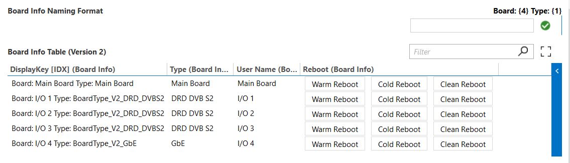
In the example above, the DisplayKey will be as follows: 'Board: (value of column 4 (User Name)) Type: (value of column 1 (Type))'.
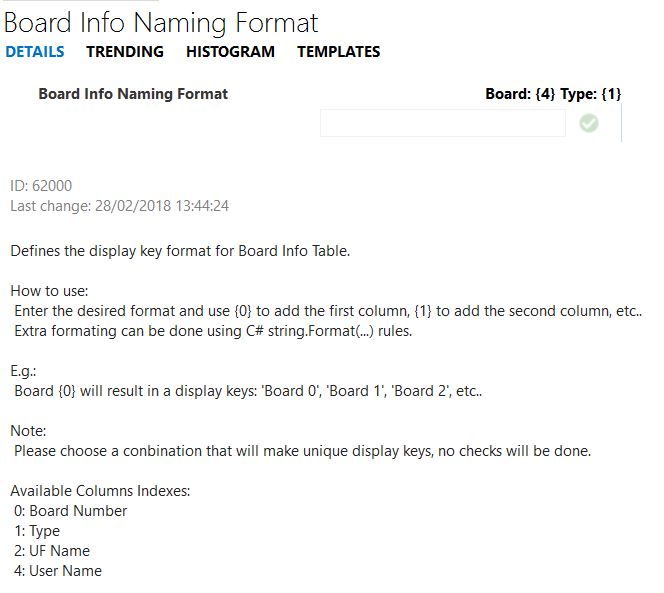
To find the column identifiers, check the corresponding Naming Format tooltips.
Based on the previous example:
Note
- Because of the complexity of display keys (based on multiple tables), the connector will not check if generated formats will produce unique values. This needs to be ensured by the user.
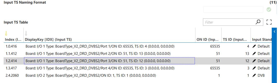
- There is dependency between tables, so if for instance the display key of Board Info Table (Version 2) is changed, this will be reflected in all tables that depend on it. In the previous example, the Input TS Table display key will be as follows:
- By default, all custom naming will be configured with the same values that were hardcoded before version 1.0.0.83. No historic data will be lost.
- From version 1.0.3.101 of the connector onwards, there is a toggle button to disable the syncing. By default, the syncing is enabled.
Usage
Overview
This page contains a tree view and is one of the most important pages in the connector. The main structure of the tree view is:
- Board
- Port
- Input/Output branch
- Transport Streams
- Services
- PIDs
Each level has its own set of specific tabs. Some are generic, like the Alarms tab, where the alarms can be viewed that were generated by the DCM and are related to that Board, Port, TS, etc. Others are more specific, such as information about ECM PIDs.
Note
At the Board level, there is a special node called the Main Board. This is used to display general alarms and license information.
General
This page contains general information about the system, such as the System Name, Serial Number and Module Info. One of the most important parameters is the Current Activation Mode, which indicates if the system is online or not. Other important information includes Licenses and SNMP Settings. Note that both of these are related to Cisco DCM and not to Skyline or the connector.
Note
If event-based polling is enabled on the Driver Settings page, the connector will automatically add the IP address of the DMA and the public SNMP community of the element in the SNMP Trap Destinations table.
Alarms
This page contains an Alarm Overview table where you can find the alarms available via the web interface in the DCM. Note that these have no direct relation to alarms generated using alarm templates in DataMiner.
Below the overview table, there are three page buttons that hide the tables containing the base information used to populate the alarm overview table. These tables are not intended for use in daily operations, but can be used to track down issues when an alarm is not shown or is incorrectly shown in the overview table.
Note
It is possible that not all alarm names can be selected in the alarm template. This is because each alarm name is linked to a number, and the name has to be added as a discrete value in the connector. Since alarms/numbers can be added when firmware is upgraded or cards are added, the discrete list can become outdated. As such, if a discrete is missing, it will not be possible to create an alarm for that name using the AIT - Name column. Version 1.0.0.20 should contain all possible alarms for DCMs using firmware version V13.00.00. If there are missing alarms, please send the "DCM Alarms VXX.XX.XX.xls" file that comes with the DCM to Skyline Communications, and request to sync the discretes with that file.
Backup Settings
This page contains the built-in backup settings of the DCM device. When configured, a heartbeat will be sent between the redundant devices, which can activate the backup device when the connection is lost between the devices.
Take/Restore Backup
This page can be used to take or restore a backup.
A backup contains the complete configuration of a device. When you take a backup, it will always contain all settings, but when you restore a backup, it is possible to exclude some of the settings.
Backups are usually stored on the local DataMiner Agent. The default folder is the Windows %Temp% folder.
Important
While you are taking a backup, all other polling is set on hold. Taking a backup should only take at most 30 seconds in most circumstances; however, it is possible that it takes up to several minutes. Keep this in mind if you decide to take regular backups using the Poll Manager or an automation script. Usually, the time it takes to complete a backup does not change, so you can first take a backup manually and see how long it takes, and then decide if this is acceptable. However, the duration can change if you modify many streams and settings, so it is best to test this after the DCM is fully (re)configured.
Export/Import File
On this page, you can export or import a device configuration to or from a .csv file.
The functionality on this page is similar to that of the page Service > Configuration of the web interface of the device.
To export a configuration:
- Select the configuration by selecting True or False in the corresponding table.
- Fill in the path to the file where the configuration will be stored.
- Click the button Export Muxing Conf. or Export Alarm Conf., depending on which configuration you are exporting.
To import a file, fill in the path to the file where the configuration is stored, and click Import.
Note
- This feature can only be used if the web interface credentials have been set on Web API Login page.
- To import a configuration file, you need to have Administrator rights.
Backup Save Path
Backups are saved in the folder/file defined by combining the Backup/Restore Directory and the BS Backup Save Name. This means you can leave the Backup/Restore Directory empty and fill in the complete path in the BS Backup Save Name parameter.
Alternatively, you can also:
- set the Backup/Restore Directory to C:\Skyline DataMiner\Documents\CISCO DCM\Europe Main\
- set the BS Backup Save Name to Backups\Full Backup.tgz
- set the BS Restore Path to Backups/Approved/Full Backup.tgz
Restore Save Path
When a backup is restored, the full path of the file to restore is a combination of the Backup/Restore Directory and the BS Restore Save Name. This makes it possible to select a file without having to alter the file name used to take a backup.
Taking or Restoring a Backup
To take a backup:
- Click the Take Backup button.
- Verify the BS Backup Save Path Validation parameter and the BS Backup Status parameter to follow up the status/progress of the backup, and to get more information in case there is an error.
- In case of errors, check the element's log file for more information.
To restore a backup:
- Click the Restore Backup button.
- Check the BS Backup File Valid and BS Restore Status parameters.
- In case of errors, verify the log file for more information.
Note
- You should always set BS Backup Scope and BS Restore Scope to ALL.
- The maximum backup size is limited to 20 MB, and the maximum duration before the backup should be received is 5 minutes. This is hard-coded in the connector. (The typical size of a backup is approx. 3 MB.)
Statmux (SMX36)
The Statmux page contains settings and data tables related to Statmux parameters coming from or required for the collaboration with another Statmux DCM (CISCO D9036).
On this page, you can see which settings are used to retrieve the Statmux information (Community Name, Multicast IP and UDP Port), information about the QoS settings, a page button revealing the VSE Backup table and a page button (Overview) revealing data from the Pools, Encoders and Controllers table.
The page also contains page buttons that lead to the raw data tables used to create the Statmux Pools and Statmux Encoders trees on the next pages. Note that this data cannot be found on the Table Data page because the Statmux section is considered a separate part of the connector.
Statmux Pools
This page contains a tree view displaying information about Cisco D9036 (Statmux DCMs) devices connected to the DCM. The structure of the tree is:
- Controller
- Pool
- VSE
Note
There is a dummy node for the Controller and Pool level, so that a list of VSEs can be shown that are not part of a pool.
Statmux Encoders
This page is closely related to the Statmux Pools page and contains some of the same information, presented in a different manner. Here, the structure of the tree is:
- Encoder
- VSE
Driver Settings
This page is important when creating a DCM element. It shows the IP addresses used for IIOP communication. The first IP address is automatically retrieved from the element settings and can only be changed by editing the element itself. The second Management IP Address is optional. The ports can also be edited, though in most circumstances these should be set to 5003.
Several page buttons allow access to other important settings:
Network Error
On this subpage, it is possible to select how network errors are handled. There is also a setting that indicates if a network error is detected. It notifies the user when the connector cannot contact the DCM using the IIOP communication protocol.
When the device becomes unreachable, commands will take a long time to go into timeout, which could seriously affect the proper operation of the element and even of other elements. Other DCM elements will most likely be affected, but the effect may not be limited to those elements alone. Over time, the connector has been continuously optimized to reduce its influence on other elements as much as possible, to a point that the default setting for the Action After Network Error can be used without much risk. Nonetheless, it is advisable to change this from Continue Normal Operation to Start Ping Procedure.
The difference between the two choices is explained below.
Continue Normal Operation: When you select this option and a network error is detected, the connector will continue to try to execute each command that needs to be polled according to the Poll Manager. This will fail over and over again until the connection is restored. When a command fails due to a network error, the command will be considered to be "not executed" and will remain in the execution queue. This means that every time the poll group is triggered, the command will be executed again. Theoretically, this is every second. In practice, it can take up to 10 seconds before the IIOP engine detects a network. But when many commands are scheduled, this could lead to an RTE.
Start Ping Procedure: This option was introduced to counter the symptoms described in the default option. It stops polling commands the moment a network error has been detected. The connector will then start sending Ping messages to the Management IP Address 1 until they return with success. The advantage of this option is that RTEs are avoided and the connector becomes more responsive. The disadvantage, however, is that it only polls on one of the IP addresses instead of both and that the connector will not recover when a firewall blocks ping messages. This is why this is not the default option. So before you select this option, make absolutely sure that ping messages are not blocked by a firewall.
Note
- When for some reason IIOP messages are blocked, but ping messages succeed, pinging is preferred over continuing normal polling, because not all commands will be tried in every poll cycle. (Only one will be tried.)
- It is also possible to set the interval to ping the device in the Poll Manager. To do so, set the PM - Poll Interval for the Ping Procedure command to a custom value. The maximum interval is 10 minutes, and the minimum interval is 5 seconds (= default).
IIOP Login
This subpage can be used to set the credentials required to communicate with the DCM over IIOP. By default, for devices using firmware versions prior to 8.5, the connector will use the username and password guest/guest. However, in more recent firmware versions, the default security settings have changed, so that an IIOP-enabled account is no longer available by default. This means that an account has to be created manually before the connector can be used to poll data. For more information on how to create the account, refer to the section "Verify IIOP Credentials" above.
Note
- Up to version 1.0.0.87 all DCM elements on the same DMA must use the same credentials!
- From version 1.0.0.87 onwards, the parameter IIOP Share Credentials Between all Elements in DMA controls the credentials synchronization. If this is set to Enabled, all elements on the same DMA will use the same credentials (similar to the behavior with previous versions of the connector). If this is set to Disabled, each element will have its own credentials.
- The password is sent to the device in plain text, so a simple Wireshark session can easily reveal the password. Consequently, it is advisable not to use a password that is also used for other (more secured) resources. This is also the reason why only one password is used.
Web API Login
On this subpage, the Web API credentials can be filled in.
These credentials must be filled in in order to enable the import and export of configurations from a .csv file.
FEC Board Check
If you enable this feature (disabled by default) on the Configuration subpage, this will force the polling of the FEC data (from version 1.0.3.66 onwards).
Group Config
This page has only one parameter, but it is important to manage several DCM elements. When an element is added in a group, some settings will automatically be synced between all elements in that group. This means that when an element joins a group, it will start using the settings as defined in the group. A new group can simply be created by typing a new name in the drop-down box. In that case, the settings of the element will be used for all other elements that belong to or are added to that group. To quit a group, select *NONE*. To update the list of available groups, click the Refresh button.
A list of parameters synced by joining a group:
- Action After Network Error
- [Table: Poll Manager] Status
- [Table: Poll Manager] Poll Interval
- DCF: Include Alternate Sources
- DCF: Include Merged Sources
- DCF: Include Backup Sources
- DCF: Include Component Sources
A list of parameters to be added to this list are:
- Allow Soft Disable
- Block Thread - Time Out Span
- Block Thread - Poll Wait Time
- Allow Event Based Update of Backup Service Table
The settings of a group are saved in an .xml file located in the folder C:\Skyline DataMiner\Documents\Cisco DCM\GroupName].GroupConfig.xml. They can be downloaded from any DCM element via the Documents page. It is advisable to take a backup after all settings have been configured. Though making manual changes is not advisable, it is possible, and such changes will be picked up by the elements as soon as they are saved.
Note
It is not possible to only sync some of the parameters. Either an element is part of a group and all parameters are synced, or it is not and no parameters are synced (excluding connector config parameters, which are always synced).
Event-Based Polling
This page currently contains one toggle button to configure if the content of the Backup Service Table should be refreshed when an SNMP trap is received that indicates a (possible) change. By default, this is disabled, in order to prevent a heavy load in case of an event storm.
Note
- In the future, this parameter could be replaced by a table and multiple traps could be used to refresh some commands in the Poll Manager.
- If event-based polling is enabled and the command Get SNMP Settings is enabled in the Poll Manager, then the connector will automatically check and, if necessary, add the IP address of the DMA in the trap destinations table. However, it is still advisable to check if the SNMP settings are properly configured on the DCM itself, especially if the SNMP settings are not polled.
Event Forwarding
This is a special feature that can be used to forward some events to another element. It is only of use in some specific situations. To make sure that there is no unnecessary load on your system, the default value of the parameter Event Forwarding Table - Master Enable Polling is Disabled.
Simulation
This page allows you to create or load simulations into an element.
To create a simulation:
- Go to an element that is polling a real device and click Save.
- A file with the name "simulation.xml" will be created in the folder "C:\Skyline DataMiner\Documents\CISCO DCM\Selected Element Name]\
To load a simulation:
- Create a test element and assign a localhost as polling IP.
- Copy the file "simulation.xml" to the following folder: "C:\Skyline DataMiner\Documents\CISCO DCM\Name of Element created in previous point]\
- Click the Load button.
Note
- A simulation file should NEVER be loaded into an element that is polling a device.
- This feature has been added for debug purposes only and should only be used if someone at Skyline explicitly requests such a simulation file.
- The created file contains a lot of information about the device and the setup of your system and is not encrypted in any way.
- This does not simulate any kind of communication with devices; it only populates a table with information present in the file.
DCF
This page contains several parameters related to the DataMiner Connectivity Framework. Please refer to the "DCF" section at the end of this document for more extensive information.
The page contains 4 DCF-related configuration parameters:
- DCF: Include Alternate Sources
- DCF: Include Merged Sources (Requires: alternate sources)
- DCF: Include Backup Sources (Requires: merged sources & alternate sources)
- DCF: Include Component Sources
The configuration of these parameters is automatically distributed to the other elements in the same group config as the element. In addition, enabling one of these features may cause one or more polling commands to be automatically activated as well. For example, activating the backup sources will automatically enable polling for alternate, merged and backup sources (when the Update DCF command is enabled).
This page contains a Reset button. Click this button to remove all internal (managed) connections created by this connector. This can for instance be of use when the connections may no longer be up to date. However, note that this button will only remove connections, and not recreate them. To recreate the connections, either click Update DCF or click the Refresh All button on the Manager page.
Finally, the page contains a table with all the keys of the physical ports in the element's interface table. External connections should always be made to those ports, and never to a "virtual" interface. The format of those keys is "XY.Z", where:
- X = "I" for input-only ports, "O" for output-only ports, or "B" for IO ports (Bidirectional).
- Y = the board number (1-based, 0=chassis).
- Z = the port number (0-based).
Manager
The manager page contains the Poll Manager table, which is very important. Via this table, polling for certain commands can be enabled or disabled and the poll interval can be set (within predefined limits). Most of the commands are directly linked with a table.
Six columns are displayed in the Poll Manager table:
- Description: Contains the description of the command.
- Status: Shows whether the command is enabled or not.
- Poll Interval: Contains the interval between two polls.
- Execution Counter: Contains a number indicating how many times the command has been executed since startup.
- Last Executed: Contains a timestamp indicating when the command was last executed.
- Actions: Allows you to poll the command again outside the normal polling cycle.
The status of a command is either Enabled or Disabled. However, some commands cannot be disabled by the user. These are displayed as [Enabled]. This is for instance the case for Get Boards and Get Ports.
To enable a command, you can set the Status column to Enabled; however, note that this does not guarantee that the command will actually be enabled. It is possible that other commands also need to be enabled before a particular command can be activated. To see the required commands, check the hidden column PM - Required Commands (see "Hidden Columns" section below). If other commands are required, these should either be enabled in the correct order, or the option Enable (including parents) should be used.
The same applies for disabling commands: disabling a command will fail if there is at least one other command that requires that command. However, it is also possible to stop all "child commands" using the Disable (Including Children) option.
To change the polling interval, specify a new timespan in the PM - Interval column. The value should be specified as follows: [Days].[Hours]:[Minutes]:[Seconds] However, please note:
- Days and seconds are optional.
- When a timespan is specified that is less than the minimum or more than the maximum allowed interval, the value will be rounded down or up to respectively the minimum or the maximum interval.
- If the supplied input text could not be parsed, the value will not change.
There are also some buttons to quickly change certain settings:
- Reset To Defaults: Resets all poll intervals to their default value.
- Slower: Increases all poll intervals by 10%, within the limitation of the maximum allowed interval.
- Faster: Decreases all poll intervals by 10%, within the limitation of the minimum allowed interval.
- Refresh All: Refreshes all data for which the command is enabled.
- Disable All: Disables all commands, except those that cannot be disabled.
- Enable All: Enables all commands.
- Allow Soft Disable: Only available in versions prior to 1.0.0.20, along with extra status options Enabled (Strong) and Disabled (Soft). These were meant to allow the connector to disable polling for certain commands in case it was sure no changes would happen in the response. (For example: if no CAM cards are present, polling the status would always return the same (error) value.) However, the connector has been improved in such a way that this feature has become superfluous and would only add unnecessary strain to the system. It was removed by renaming the discretes and hiding the Allow Soft Disable parameter, which keeps the connector backwards compatible, but also means that in the alarm template two options with the same name are shown. If you want to activate alarms on the Status, activate monitoring on both options.
Hidden Columns
There are some columns in the Poll Manager table that are hidden by default. These can be made visible to reveal more information about the commands.
To do so, using a DataMiner version prior to DataMiner 9.6.4:
Place the mouse cursor between the column headers of Description and Status.
When the cursor changes into an indicator like this, "<-||->", double-click to reveal the first hidden column.
Repeat this procedure to show more columns, until the following columns are displayed:
PM - Default Interval
PM - Min Interval
PM - Max Interval
PM - Default State
PM - Required Commands
To do so, from DataMiner 9.6.4 onwards:
Right-click the table header, select Columns and then select the following columns:
PM - Default Interval
- PM - Min Interval
- PM - Max Interval
- PM - Default State
- PM - Required Commands
Table Data
On this page, you can access several tables using page buttons. You can also view the information contained in the tables elsewhere by using the tree view or via another page. However, the tables on this page make it easier to compare information. For example, to compare the bitrates of a service with those of another service, it is easier to use the table view than to look for the separate bitrates for each service using the tree view.
Custom Adaptations
At the request of customers, Skyline can add customer-specific features in this connector, which may result in extra tables, polling, a higher CPU load, etc. However, to minimize the impact of such customizations, by default, these extra features are disabled and hidden. They are numbered as follows: "HF1", "HF2", etc. This is short for "Hidden Feature N". You can find these features on the Table Data page by clicking a page button displaying the HF number. It is assumed that the customer who ordered the feature will know where to find it or will use a custom visual overview to make it more easily accessible.
It is usually not possible to request a change to a hidden feature that was not ordered by your company. This is because those features are usually very specific and are used by automation scripts, visual overviews, other connectors, etc., so that changing even a small detail could potentially break the system of another user. However, the company that ordered a feature can request changes to that feature and other customers will not be considered when the change is implemented.
The currently implemented customizations are listed below.
Event Forwarding
This customization is exceptional, in that it is considered "potentially interesting for other customers", and as a consequence has no sequence number. Instead it has a page button, Event Forwarding, on the Driver Settings page. It is used to trigger actions on another element (using another connector) in an event-based manner.
Currently, the following events can be forwarded:
- Alarm severity changes on the port table.
- Alarm severity changes on the output transport stream table
- Alarm severity changes on the transport stream bitrate table
- Each time a backup has finished.
Note
The alarms used for this feature are not those from the alarm table, but the severity of the alarms as defined by the alarm template.
To activate this feature:
Enable the Master Enable Polling parameter.
Activate the specific event in the Event Forwarding Table.
In order to configure the elements to which the event must be sent, set the Targets field to DMA\EID\PID. Multiple targets can be separated by a semicolon (";").
When the event is forwarded, a remote parameter set will be executed on the targeted parameters. For alarm changes, the set will have the format "DMA\EID\PID\LEVEL\INDEX", where the DMA, EID and PID are of the local (\source) element. In case of a backup, the format will be either "DMA\EID\ERROR [Backup Not Saved]" or "DMA\EID\PATH]", where PATH is the full path to the file on the DMA.
HF1 - Service In Alarm
This feature adds an extra alarm table that is reduced to a small subset of the alarm table parameters. Only alarms related to services are displayed, and for these only a number of the columns from the alarm table are shown.
HF2 - Switching Parameters
This feature adds an extra table in which a row is added for each port on the DCM. The table has the following columns:
- Key: Formatted as [board].[port] (same as in the port table).
- Name: The same name as in the port table.
- Connected Device ID: Can be set by the user, in the format "DMA/EID". When set, the connector will check if the element exists, and if so, it will set the name of the element in the "Connected Device Name" column. Otherwise, the columns "Connected Device ID", "Connected Device Name" and "Connected Device Port" are cleared. The value of this column is saved.
- Connected Device Name: Set by the connector when a valid element ID is set and refreshed on element startup.
- Connected Device Port: A custom string. No checks are done by the connector. (Saved)
These parameters are used by automation scripts. Records in this table are not deleted, even if boards or ports disappear from the system.
HF3 - Service Info
This feature adds a table in which a row is added for each service modulo 100 in the backup service table. The row has a key equal to the service ID modulo 100 and a display key which consists of the key and a custom name separated by a dash ("-"). It also contains a Status column, which indicates whether there is at least one backup active.
Also note the following:
- The user name is saved, and rows are not deleted, unless you set the name to "[deleted]".
- When no services are found for an existing "ID range", the status is set to "None Present".
- When the backup service table is no longer polled, the status is set to "Not Available".
- When the HF is activated, the service backup command will also be activated if it was not yet active.
HF4 - Output TS Bitrate Used (Percentage)
When enabled, this feature calculates how much of the allowed bandwidth an output transport stream uses. This is calculated by dividing the OTSB - Total Curr. bitrate from the Output TS Bitrates Table by the OTS - Bitrate column in the Output TS Table. The results are stored in a new table, the Output TS Extension table. The key is the same in all three tables. Note that this feature increases the processing load for the system somewhat.
HF5 - Online Service Schedule
This feature is used in combination with several new columns in the alarm overview table to help decide the relative importance of alarms. It can be accessed via Table Data button HF 5.
With this feature, you can indicate when each service is online in the Service Online Schedule table. To do so, add one or more records for each service, making sure that the SOS - Service Name column is the same as the Alarm - Service Name column in the Alarm Overview Table, but without the "(SID)". Note: To have the Service Name in the Alarm Overview table, Get Input Services and Get Output Services must be polled. You can enable this in the Poll Manager table on the Manager page.
The time when the service is "online" is recurrent and can be set on a weekly basis. As such, each record has a start day, an end day, a start time, and an end time.
A line can be set as Always On Air or Never On Air, in which case all time fields (start day and time, and end day and time) are set to this value. If you select the same start and end, the service will automatically be set to Never On Air. There is also a column that indicates whether the service actually exists on the device.
Services that are not configured in this table are considered "Always On Air". If there is a record for a service with "Never On Air" and another one with a valid start and end time or the value "Always On Air", then the service will be considered on air during that period.
The context menu on the On-Air Services Scheduler
- Add New Row: To add a row: right-click the table and select the "Add Row" item in the context menu. You will be asked for the name of the service you want to add.
- Add Missing Services: Looks for any service name that is configured on the device and does not have a config record. A row will be added for those records and set to Always On Air.
- Delete Selected Row(s): Deletes one or more selected rows.
- Duplicate Row(s): Duplicates one or more selected rows.
- Always On Air: Sets the selected rows to Always On Air.
- Never On Air: Sets the selected rows to Never On Air.
- Refresh Service List: Can be used to update the OSS - Service Exists column. This happens automatically when you open the page by clicking the page button, and can also be triggered using the Refresh List button at the bottom of the page.
Backup\export
To take a backup of the settings, right-click the table and select Other\Export Table.
Import
To import a schedule, select a file in the OSS - File To Import field below the table. There is a drop-down list with all available .csv files in the selected Import Folder. Alternatively, you can also set the full path to any file accessible to the DataMiner Agent.
Note that an import will delete all already available records and replace them with the contents of the import file.
Import format
There are a few rules that the import file must comply with, and some things that the creator must be aware of. However, if the table was exported from DataMiner, these are automatically as they should be.
Though this is advisable, the file does not have to have the ".csv" extension; however, it must be formatted as a .csv file.
The first two lines are mostly ignored by the connector.
Regarding the first line:
The content of the first line is used to identify the separator, which can be either a semicolon (";") or a comma (",").
Aside from this, the content of the first two lines is completely ignored.
You can use the first line to indicate the titles of the columns, in order to make the file more readable. However, note that the order of the columns cannot be changed, so if you just switch two of the column titles, this does not mean that the connector will change these accordingly.
Regarding the second line:
The content of the second line is completely ignored by the connector, so make sure not to put any rows here with content that needs to be imported.
Regarding all other lines:
All the other lines in the file are considered possible data lines. They will be parsed and, if parsing was successful, result in a new row in the table.
A (valid) record must be formatted like this: [IGNORED];[SERVCE_NAME];[START_DAY];[START_TIME];[END_DAY];[END_TIME]
This is the purpose of each column:
IGNORED: The first column is not used in the import. When you export a table, this column will have the key of the record in that table. This will not necessarily be the same key after importing.
Service Name: The name of the service as it is displayed in the ALARM - Service Name column in the Alarm Overview table, but without the service identifier.
Start Day: The day of the week when the service goes online.
You can use any of the following values:
The number indicating the day of the week. '0' is Sunday, '1' is Monday, etc.
The day of the week in English and in text format: "Sunday", "Monday", etc. (not case sensitive)
The abbreviation of the days: "Sun", "Mon", "Thu", etc. (not case sensitive)
If the server is set to the local culture, the day of the week and abbreviated names in your own language (not case sensitive). For example, if Server Culture is set to "nl" (Dutch): "Zondag", "zo", "Maandag", "ma", etc.
Always On-Air or Never On-Air.
Start Time: The time when the service comes online, formatted as:
HH:mm, where HH is 24-hour format;
or Always On-Air or Never On-Air.
End Day: The day of the week when the service goes offline. Formatted in the same way as the Start Day.
End Time: The time on the End Day when the service goes offline. Formatted in the same way as the Start Time.
Note
- Optionally, cell values can be enclosed in double quotations marks ('"').
- If one of the time columns contains Always On Air or Never On Air, all columns should.
Example CSV file for import
Below is an example of a .csv file used for import. The text in red consists of comments, which have no actual effect on the import.
INDEX;Service Name;Start Day;Start Time;End Day;End Time <- First row: contains more semicolons (;) than commas (,) so the rest of the file will be parsed using the ';' separator
------------------------------------------------------------------------------------- <- this line is completely ignored
BBC: <- first data line, but ignored here because it contains a comment.
"0";"BBC 1";"Wednesday";"14:00";"Wednesday";"14:50"; <- this is how it would be formatted if exported.
;BBC 2;0;0:0;0;0:0; <- This is probably the shortest possible valid record. Note that start and end time are the same; therefore the service is always online.
1;BBC 3;monday;08:00;friday;16:00; <- The index '1' will be ignored and is therefore optional
<empty line: is ignored>
National Geographic Channel: <- a comment, is ignored
;Nat GC;monday;08:00;monday;16:00 <- again a valid line
;Nat GC;tuesday;08:00;monday;16:00
;Nat GC;3;08:00;3;16:00; <- day names are replaced by numbers
;Nat GC;4;08:00;4;16:00
;Nat GC;5;08:00;5;16:00

Info channel
;Info;Always On-Air;Always On-Air;Always On-Air;Always On-Air<- All columns are required, otherwise the row will be ignored.


File Made By Skyline @[15:30 PM 17/09/2014]

Designed for import in Cisco DCM connector.
Will tell the element when a service is online.

END OF FILE
DCF
The Cisco DCM connector has been updated to support the DataMiner Connectivity Framework (DCF). Like all the other features, this can be enabled or disabled in the Poll Manager. (Row description is Update DCF.) This feature was introduced in version 1.0.0.23 but had a major revision in version 1.0.0.26. DCF should not be used in versions before 1.0.0.26.
The minimal DataMiner software version required for DCF is version 8.5.4. In older versions, the DCF feature will automatically be disabled (even if it is enabled in the Poll Manager), and it will not be possible to change the DCF-related configuration parameters on the DCF pop-up page. (On the page Driver Settings.)
The DCF feature is a complex and powerful design that allows the user to track the source(s) of any output signal(s). To make this possible, the connector creates several internal (virtual) interfaces representing different levels. To get the most out of the DataMiner Connectivity Framework, it is important to understand how this works.
To create the connections, the connector uses the following sources:
- Port Table
- Input Transport Stream Table
- Input Service Table
- Input Component Table [Optional]
- Output Component Table [Optional]
- Output Service Table
- Output Transport Stream Table
- Alternate Sources Table [Optional]
- Merged Sources Table [Optional]
- Backup Services Table [Optional]
Polling for these tables will need to be activated in the Poll Manager before those sources can be used by DCF. The connector will automatically enable the required poll commands when DCF or one of the optional features is activated. Likewise, when one of the required tables is disabled in the Poll Manager by means of Force Disable, DCF will automatically be disabled. This does not apply for the optional tables. When polling for the optional tables is disabled while DCF is active and the configuration parameters include the use of these tables, an information event will be generated to indicate that DCF will not be complete.
To enable the optional data sources:
Go to Driver Settings.
Click the DCF button.
A pop-up page will be displayed.
Set the parameter DCF: Include xxx Sources to Yes.
Note that all DCF-related settings are automatically propagated to all elements using the same group config. (See Section: Driver Settings > Group Config.)
The DCF Linking Engine
The following sections explain the internal workings of the DCF linker used to connect inputs to outputs.
Note
- When a "Source Service" is used, this can be a service from the Input Service Table or from the Output Service Table. The system will first check the Input Service Table, and if the reference is not found there, it will try to find the service in the Output Service Table. This can be the case when the source signal is the result of a processing step. In the web interface, this is the equivalent of a source coming from the processing tree instead of the input tree.
- When signals from this processing tree are used, it may be necessary to poll the CAM Config command in order to allow a full backtrack of the output signals to the input. This will not be enabled automatically, as this command will inject additional "virtual" ports in the port table, which in turn adds extra transport streams, services, etc.
Default
As mentioned before, the connector will generate virtual interfaces for every input and output transport stream, service, etc. In essence, such a virtual interface will be generated for every row in every table mentioned in the data sources above. These will be linked from input to output using the available foreign key columns in those tables. So an input port is linked to every input TS that has an FK to that port, etc. When only the required tables are used, every output service will be linked to a source service.
The connections between a port and a transport stream will have the following properties:
MC: This is a MultiCast IP address and port format: x.x.x.x:p.
VLAN: This is a number indicating the Virtual Lan ID.
Note: This can automatically be retrieved from the device if polling for the Output VLAN command is activated.
For input VLANs, this can optionally be defined manually in the Input TS VLAN Config table (Table Data page > button VLAN: Input).
ONID: This contains the OnID property for the transport stream.
Alternate Sources
When alternate sources are included, extra connections will be created between an output service and a "source" service. This is done by adding a connection between the source interface and the alternate interface and from the alternate interface to the output interface. This first connection has an attribute "IsBackup=False" and the second connection (from alternate to output) has no attributes.
Depending on the nature of the source service (processing stream or input stream), the signal will be linked to an interface of the output or input service table. Alternating sources can e.g., be used for outputs containing signal X during the day and signal Y during the night. You can find them in the web interface by right-clicking an output service in the "Service" tab and selecting "Advanced Configuration". The alternate sources are especially important because merged services and backup services are linked to alternate sources instead of directly to output services.
Merged Services
Merged services can be used if an output service contains components from different input services. A connection is made from a source service to a virtual interface generated by the merged service table, and from that virtual interface to an alternate interface.
Backup Services
Including backup services will add a connection from a source service to every interface (= row in the service backup table) and a connection to a merged or alternate interface. A backup service for a merged service will connect to a merged service, and a backup service for the main service of an alternate source will connect to that alternate service.
On the source connection, two extra attributes will be defined:
- IsBackup: Indicates that this is a backup source. Format: True
- IsActive: Indicates if this backup is active. Format: True or False.
When this data source is enabled, the IsActive property will also be added to the source connection of an alternate interface and the merged interface.
Component Sources
When component sources are used, extra connections will be created between interfaces from the "Input Service" table and "Input Component" table, between interfaces from the "Output Component" table and the "Output Service" table, and between the source components of an output component. However, to reduce the load on the system, this will only be done for elementary streams, so not for PCR, PMT or ECM components (unless a PCR/PMT component is also ES).
Connecting these relations may cause a huge load on the system, so this should only be enabled if the other functions do not suffice. An example of such a case could be the implementation of radio services, where the output starts from a locally generated empty stream and is merged with the audio components of an input source. In this case, the output service would not have a valid source reference and there would be no merged services either.
Note: Component sources are always active. These connections will not be available for inactive alternate sources.
Summary of all DCF connections and properties
Below, you can find what kind of connections can be made from each interface and what the properties could be.
Note: For connections of which the name ends with [KEY], KEY is replaced with the primary key of the destination interface.
Physical Ports
Linking other elements should be done using these interfaces.
The keys are formatted as XY.Z, where X = "I" for input-only ports, "B" for IO ports (Bidirectional) and "O" for output-only ports. Y is the board number (1-based, 0=Main board), Z is the port number (zero-based).
To "Ports" name: ./InputPort
(Only for Input or IO ports)
Ports
To "Physical Ports" name ./OutputPort
(Only for Output or IO ports)
To "Ports" name ./Mirrored
(For ports that are configured in a port pair and send the same signals.)
- Attribute: Mirrored, format: Yes
To "Input TS" name ./InputTS
Attribute: MC, format: x.x.x.x:y
Attribute: VLAN, format: x if available, NA if not available
Attribute: ONID, format: x
Input TS
To "Input Service" name ./InputService
- Attribute: Name (= System Name column)
Input Service
To "Output Service" name ./ActiveSource[KEY]
To "Input Component" name ./InputComponent[KEY]
To "Alternate Sources" name ./MainSource[KEY]
(Optional; must be enabled)*
Attribute: IsBackup, format: False
Attribute: IsActive, format: True or False
To "Merged Sources" name ./MergedSource[KEY]
(Optional; must be enabled)
Attribute: IsBackup, format: False
Attribute: IsActive, format: True or False
To "Backup Sources" name ./BackupSource[KEY]
(Optional; must be enabled)
Attribute: IsBackup, format: True
Attribute: IsActive, format: True or False
Input Component
(Optional; must be enabled: DCF: Include Component Sources)
To "Output Component" name ./SourceComponent[KEY]
Output Component
(Optional; must be enabled: DCF: Include Component Sources)
To "Output Service" name ./OutputComponent
- To "Output Component" name ./SourceComponent[KEY]
Output Service
To "Output TS" name ./OutputService
- Attribute: Name (= Output Service Name column)
To "Output Service" name ./ActiveSource[KEY]
To "Alternate Sources" name ./MainSource[KEY]
(Optional; must be enabled)
Attribute: IsBackup, format: False
Attribute: IsActive, format: True or False
To "Merged Sources" name ./MergedSource[KEY]
(Optional; must be enabled)
Attribute: IsBackup, format: False
Attribute: IsActive, format: True or False
To "Backup Sources" name ./BackupSource[KEY]
(Optional; must be enabled)
Attribute: IsBackup, format: True
Attribute: IsActive, format: True or False
Output TS
To "Ports" name ./OutputTS
Attribute: MC
Attribute: VLAN
Attribute: ONID
Alternate Sources
(Optional; must be enabled: DCF: Include Alternate Sources)
To "Output Service" name ./Alternate
- Attribute: IsActive, format True or False
Merged Sources
(Optional; must be enabled: DCF: Include Merged Sources)
- To "Alternate Sources" name ./Merged
Backup Sources
(Optional; must be enabled: DCF: Include Backup Sources)
To "Merged Sources" name ./Backup
If this connection exists, the connection to the alternate source will not exist.
To "Alternate Sources" name ./Backup
If this connection exists, the connection to the merged source will not exist.