CPI K4D72C
This protocol is intended for the polling of several status and fault/alarm parameters on CPI K4D72C devices.
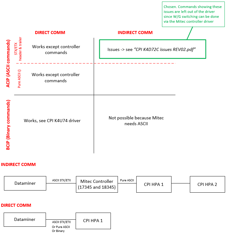
The protocol uses the CPI serial protocol in ASCII mode with STX/ETX bytes as delimiters. All packets end with the checksum byte (LRC).
About
Version Info
| Range | Key Features | Based on | System Impact |
|---|---|---|---|
| 1.0.0.x [SLC Main] | Initial version | - | - |
Product Info
| Range | Supported Firmware |
|---|---|
| 1.0.0.x | - Front Panel Boot Kernel Software Version: 03.00.19 - Front Main Program Software Version: 03.01.85 - Power Supply Controller Boot Kernel Software Version: 03.00.03 - Power Supply Controller Main Program Software Version: 03.01.40 - RF Controller Boot Kernel Software Version: 03.00.03 - RF Controller Main Program Software Version: 03.01.46 - External Interface Controller Boot Kernel Software Version: 03.00.03 - External Interface Controller Main Program Software Version: 03.01.62 - CAN Communication Level Key Version: 03.01.31 |
System Info
| Range | DCF Integration | Cassandra Compliant | Linked Components | Exported Components |
|---|---|---|---|---|
| 1.0.0.x | No | Yes | - | - |
Configuration
Connections
Serial connection
This connector uses a serial connection and requires the following input during element creation:
SERIAL CONNECTION:
Interface connection:
- IP address/host: The polling IP of the device, e.g., 127.0.0.1.
- IP port: The IP port of the device, e.g., 4016. Required.
- Bus address: The bus address of the device. Required. Uses the format <Node><Destination>, e.g., 3031 for Node 0x30, Destination 0x31, or <Destination>, e.g., 31 for Destination 0x31. The node refers to the controller (e.g., Mitec 17345), the destination refers to the HPA itself.
System Setup
How to use
The element consists of the data pages detailed below.
General
This page contains general information such as the ID Version, Status Data Check, Control Point, Switch Controller Inhibit, Drive Power, etc.
Page buttons provide more detailed information: RF, Beam, Time, System Information, Amplifiers Channel Number, etc.
Status
This page contains status parameters such as Power Saver On, Channel Changer Inhibit, Linearizer Fault, and Switch System Not Loaded Alarm.
Page buttons provide more detailed information: Beam Status, PS Status, Heater Status, SIM Status, UPC Status, RF Status, High Alarms, etc.
Meter Readings
This page contains various measurements from the device, including Attenuation, Heater Current, Inlet Temperature, Reflected RF, etc.
Alarm Trip Point
This page contains information relevant for alarm monitoring, such as Inlet Humidity, Outlet Temperature Alarm, High RF Output Alarm and Low RF Output Alarm (Trip Point), etc.
Fault Trip Point
This page contains information related to faults, such as Beam Voltage During Standby Fault, Beam Under Voltage Fault, Heater Over Voltage Fault (Fault Trip Point), High RF Output Fault, etc.
Miscellaneous
This page contains miscellaneous information such as the Attenuator Set Point, Linearizer Gain, Power Tracker Back Off, Nameplate Beam Voltage, etc.
Switch Controller
This page contains switch controller status information (W/G Switches positions, KHPAs Errors, Switch Control point and W/G Switch controller mode). The W/G switch positions and controller mode can also be configured on this page.
The Polling Switch Controller Status toggle button allows you to enable or disable polling of the switch controller status data.