Generic Matrix Virtualization
About
The Generic Matrix Virtualization connector allows you to control and abstract multiple routing matrices into a single virtual matrix, supporting various advanced features like concatenation, tie lines, and external loop management (processing units).
Depending on the version, the connector uses element connections or subscriptions to retrieve data from the source matrices.
The connector also provides different possibilities for alarm monitoring and trending.
Version Info
| Range | Key Features | Based on | System Impact |
|---|---|---|---|
| 3.0.0.x | Concatenation, tie lines, and dual stream. | - | - |
| 4.0.0.x [Obsolete] | - Label management - Tie line management - Actions |
- | - |
| 4.0.1.x [SLC Main] | Supports subscription as an update channel. | 4.0.0.42 | Some configuration is required to enable subscriptions (see below). |
Range 3.0.0.x
About Range 3.0.0.x
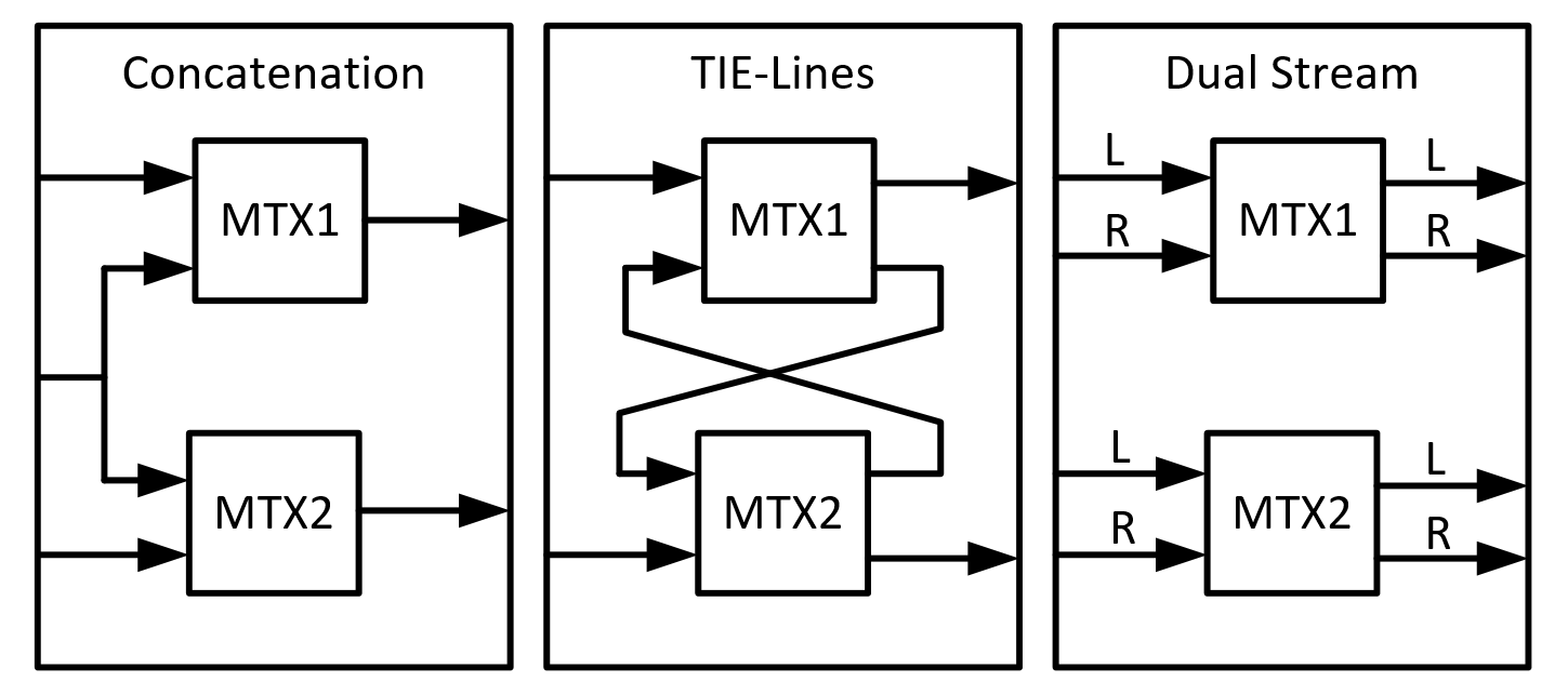
This range allows you to select one of the following functionalities: Concatenation, TIE-Lines, and Dual Stream.
Note: It is possible to put a matrix virtualization on top of another matrix virtualization to support multiple functionalities.
To be able to build the matrix virtualization on top of matrix elements (which we will refer to as children) there has to be a Status String (which indicates the state of the matrix) available on these children.
The Status String must have the following format: crosspoints list|DMA_ID/Element_ID|Write_Matrix_PID|Physical_Max_Size_Inputs In the crosspoints list, this is the content:
- position = output number
- value = input number, zero-based. If -1 = disconnected
Example of a status string: 9;5;6;4;-1;3;0|112/55|101|10
- output 0 is connected to input 9
- output 1 is connected to input 5
- output 2 is connected to input 6
- output 3 is connected to input 4
- output 4 is not connected to an input
- output 5 is connected to input 3
- output 6 is connected to input 0
- The matrix element is 112/55
- The write parameter ID is 101
- The maximum input size of the matrix is 10 inputs (0-9)
On the Settings page, the Input Data table shows an overview of all the status strings that are forwarded to the connector by means of element connections. The Format Status String column indicates if the Status String can be parsed correctly. If this state is NOK, check the format of the status string and restart the element.
CSV files are used to define which child inputs/outputs represent which inputs/outputs in the matrix virtualization.
Configuration of Range 3.0.0.x
Connections
Virtual Connection
This connector uses a virtual connection and does not require any input during element creation.
Configuration of CSV Files for Concatenation Method
For the Concatenation method, an Input and Output CSV file must be created.
The Input CSV file must have the following columns: Input;Label;Matrix;Child Input;Matrix;Child Input;.... It can optionally have the following columns at the end: External Custom 1;External Custom 2;External Custom 3;External Custom 4;X;Y;Page;Sequence. For example:
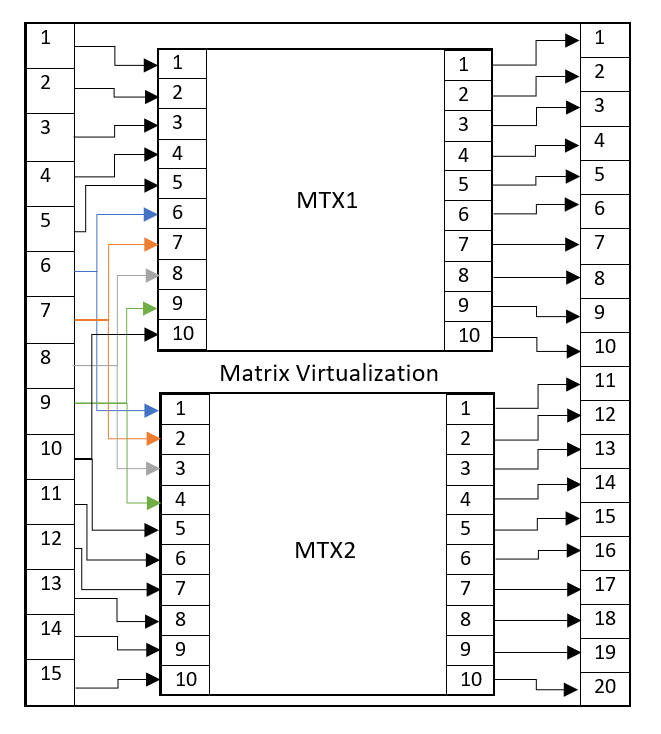
Input;label;matrix;Child Input;matrix;Child Input 1;M1 IN1;MTX1;1;; 2;M1 IN2;MTX1;2;; 3;M1 IN3;MTX1;3;; 4;M1 IN4;MTX1;4;; 5;M1 IN5;MTX1;5;; 6;X1 IN1;MTX1;6;MTX2;1 7;X1 IN2;MTX1;7;MTX2;2 8;X1 IN3;MTX1;8;MTX2;3 9;X1 IN4;MTX1;9;MTX2;4 10;X1 IN5;MTX1;10;MTX2;5 11;M2 IN1;;;MTX2;6 12;M2 IN2;;;MTX2;7 13;M2 IN3;;;MTX2;8 14;M2 IN4;;;MTX2;9 15;M2 IN5;;;MTX2;10
The Output CSV file must have the following columns: Output;Label;Matrix;Child Output. It can optionally have the following columns at the end: External Custom 1;External Custom 2;External Custom 3;External Custom 4;X;Y;Page;Sequence. For example:
Output;label;Matrix;Child Output 1;M1 OUT 1;MTX1;1 2;M1 OUT 2;MTX1;2 3;M1 OUT 3;MTX1;3 4;M1 OUT 4;MTX1;4 5;M1 OUT 5;MTX1;5 6;M1 OUT 6;MTX1;6 7;M1 OUT 7;MTX1;7 8;M1 OUT 8;MTX1;8 9;M1 OUT 9;MTX1;9 10;M1 OUT 10;MTX1;10 11;M2 OUT 1;MTX2;1 12;M2 OUT 2;MTX2;2 13;M2 OUT 3;MTX2;3 14;M2 OUT 4;MTX2;4 15;M2 OUT 5;MTX2;5 16;M2 OUT 6;MTX2;6 17;M2 OUT 7;MTX2;7 18;M2 OUT 8;MTX2;8 19;M2 OUT 9;MTX2;9 20;M2 OUT 10;MTX2;10
The above can be visualized as follows:
Configuration of CSV Files for Tie-Lines Method
For the Tie-Lines method, an Input, Output, and Tie-Line CSV file must be created.
The Input CSV file must have the same format as for the Concatenation method, as explained above. For example:
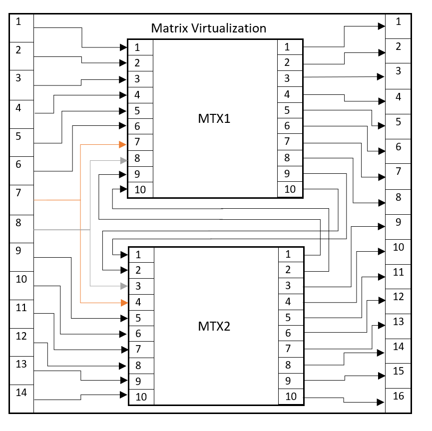
Input;label;matrix;Child Input;matrix;Child Input 1;M1 IN1;MTX1;1;; 2;M1 IN2;MTX1;2;; 3;M1 IN3;MTX1;3;; 4;M1 IN4;MTX1;4;; 5;M1 IN5;MTX1;5;; 6;M1 IN1;MTX1;6;; 7;X1 IN1;MTX1;7;MTX2;3 8;X1 IN2;MTX1;8;MTX2;4 9;M2 IN1;;;MTX2;5 10;M2 IN2;;;MTX2;6 11;M2 IN1;;;MTX2;7 12;M2 IN2;;;MTX2;8 13;M2 IN3;;;MTX2;9 14;M2 IN4;;;MTX2;10
The Output CSV file must have the same format as for the Concatenation method, as explained above. For example:
Output;label;Matrix;Child Output 1;M1 OUT 1;MTX1;1 2;M1 OUT 2;MTX1;2 3;M1 OUT 3;MTX1;3 4;M1 OUT 4;MTX1;4 5;M1 OUT 5;MTX1;5 6;M1 OUT 6;MTX1;6 7;M1 OUT 7;MTX1;7 8;M1 OUT 8;MTX1;8 9;M2 OUT 1;MTX2;3 10;M2 OUT 2;MTX2;4 11;M2 OUT 3;MTX2;5 12;M2 OUT 4;MTX2;6 13;M2 OUT 5;MTX2;7 14;M2 OUT 6;MTX2;8 15;M2 OUT 7;MTX2;9 16;M2 OUT 8;MTX2;10
The Tie-Line CSV file must have the following columns: Tie-Line;Source (matrix);Source (output ID);Destination (Matrix);Destination (input ID). For example:
Tie-Line;Source (Matrix);Source (Output ID);Destination (Matrix);Destination (Input ID) 1;MTX1;9;MTX2;1 2;MTX1;10;MTX2;2 3;MTX2;1;MTX1;9 4;MTX2;2;MTX1;10
The above can be visualized as follows:
Configuration of CSV Files for Dual Stream Method
For the Dual Stream method, an Input and Output CSV file must be created.
The Input CSV file must have the following columns: Input;Label;Matrix;Child Input;Matrix;Child Input;...;Dual Stream. It can optionally have the following columns at the end: External Custom 1;External Custom 2;External Custom 3;External Custom 4;X;Y;Page;Sequence. For example:
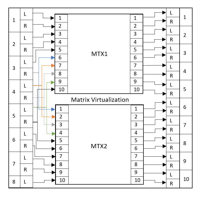
Input;label;matrix;Child Input;matrix;Child Input;Dual Stream 1;IN1 M1 LR;MTX1;1;;;MTX1:2 2;IN2 M1 LR;MTX1;3;;;MTX1:4 3;IN3 M1 L X R;MTX1;5;;;MTX1:6\|MTX2:1 4;IN4 X LR;MTX1;7;MTX2;2;MTX1:8\|MTX2:3 5;IN5 X LR;MTX1;9;MTX2;4;MTX1:10\|MTX2:5 6;IN6 M2 LR;;;MTX2;6;MTX2:7 7;IN7 M2 LR;;;MTX2;8;MTX2:9 8;IN8 M2 L;;;MTX2;10;
The Output CSV file has to have the following columns: Output;Label;Matrix;Child Output;Dual Stream. It can optionally have the following columns at the end: External Custom 1;External Custom 2;External Custom 3;External Custom 4;X;Y;Page;Sequence. For example:
Output;label;Matrix;Child Output;Dual Stream 1; OUT1 M1 LR;MTX1;1;MTX1:2 2; OUT2 M1 LR;MTX1;3;MTX1:4 3; OUT3 M1 LR;MTX1;5;MTX1:6 4; OUT4 M1 LR;MTX1;7;MTX1:8 5; OUT5 M1 LR;MTX1;9;MTX1:10 6; OUT6 M2 LR;MTX2;1;MTX2:2 7; OUT7 M2 LR;MTX2;3;MTX2:4 8; OUT8 M2 LR;MTX2;5;MTX2:6 9; OUT9 M2 LR;MTX2;7;MTX2:8 10; OUT10 M2 LR;MTX2;9;MTX2:10
The above can be visualized as follows:
Configuration of element connections
To configure the elements connections:
- On the Settings page of the element, in the Input Data table, configure the matrices you want to include in the matrix virtualization. To do so, add or delete rows via the context menu until the table contains the matrices you want to include.
- In the Cube sidebar, go to Apps > Element Connections.
- In the Element Connections app, connect the Status String (Input Data) cells from the matrix virtualization with the correct Status String parameter of the child matrices. You can add rows by duplicating the Status String (Input Data) row.
- Check in the Input Data table on the Settings page of the element if the Status String is displayed. If it is not, close the Element Connections app and open it again to see if the element connection was established correctly.
- Go to the page of the method you want to use and specify the path and file name of the necessary CSV files, as detailed above.
- Select the Method at the top of the page.
- On the Inputs/Outputs page, check if all inputs and outputs of the virtual matrix are now available. If they are not, check in the element logging to see what went wrong with the CSV import.
How to Use Range 3.0.0.x
General
On the Settings page, the Input Data table shows the status strings of the connected matrices, with the Format Status String (Input Data). It is also possible to export CSV files from the connector to save the current configuration. This export will always include the optional columns in the CSV files.
Input/Outputs
This page displays the inputs/outputs table of the virtual matrix. The XPos, YPos, Page, Sequence, and the five External Custom columns can be used in Visual Overview or for other purposes, but they are not used on the data pages.
The custom columns provide more information on the inputs and outputs for some of the methods:
| Custom 1 (Outputs) | Custom 2 (Outputs) | Custom 3 (Outputs) | Custom 4 (Outputs) | Custom 5 (Outputs) | |
|---|---|---|---|---|---|
| Concatenation | Connected Input Label | NA | NA | NA | NA |
| TIE-Lines | Connected Input Label | NA | NA | NA | NA |
| Dual Stream | Connected Input Label (L) | Connected Input (R) | Connected Input Label (R) | Dual/Mono output | Child Output Info (R) |
| Custom 1 (Inputs) | Custom 2 (Inputs) | Custom 3 (Inputs) | Custom 4 (Inputs) | Custom 5 (Inputs) | |
|---|---|---|---|---|---|
| Concatenation | NA | NA | NA | NA | NA |
| TIE-Lines | NA | NA | NA | NA | NA |
| Dual Stream | Child Input Info (R) | NA | NA | NA | NA |
The Refresh CSV page button on the Input/Outputs page opens a subpage with the Refresh from CSV button. This button will reload the inputs and outputs tables.
Note:
- Refreshing the tables may disrupt the DCF connections.
- The Refresh from CSV button is only visible for users with Administrator (level 3) access level.
Concatenation
On this page, you can fill in the location of the CSV files in case you want to select the Concatenation method.
TIE-Lines
On this page, you can fill in the location of the CSV files in case you want to select the Tie-Lines method.
The TIE-Lines table shows how many tie lines there are and how many are available.
The TIE-Line Reservation Time parameter allows you to configure the number of seconds a tie line must be reserved before the connector can assume a set failed and the tie line should be available for other sets again.
Dual Stream
On this page, you can fill in the location of the CSV files in case you want to select the Dual Stream method.
You can also change the suffixes for the Dual Stream labels here.
DataMiner Connectivity Framework - Range 3.0.0.x
The 3.0.0.x connector range of the Generic Matrix Virtualization connector supports the usage of DCF.
DCF can also be implemented through the DataMiner DCF user interface and through DataMiner third-party connectors (for instance a manager).
Interfaces
Dynamic Interfaces
Virtual dynamic interfaces:
- Input interfaces: For every entry in the Inputs table, an interface of type in is created.
- Output interfaces: For every entry in the Outputs table, an interface of the type out is created.
Connections
Internal Connections
- For every connection that is made between Inputs and Outputs, an internal connection is created.
Range 4.0.0.x
About Range 4.0.0.x
This range features label management, tie line management, and several actions.
Configuration of Range 4.0.0.x
Connections
Virtual Connection
This connector uses a virtual connection and does not require any input during element creation.
Initialization
1. Preparing the Source Matrices
Note: The source matrices need to have the latest Matrix Helper classes and parameters to be compatible.
On the Source Matrices page, right-click the table to add rows via the context menu. The table must contain a row for each source matrix you want to connect.
Optionally, you can already apply filtering on the inputs and outputs using the Input Filtering and Output Filtering columns.
If you want to use subscriptions (which is the highest-performing update method), set the Status Update Mode to Subscriptions, and configure the columns Element Name, Matrix Buffer PID, Max. Inputs, Max. Outputs, Source Table Pid, Destination Table Pid, and Park Input ID.
2. Creating Tie Lines
On the Tie Lines Configuration page, right-click the table to add rows via the context menu.
You can instruct the Generic Matrix Virtualization connector to not use certain tie lines, even though they are shown. In order to do this, you need to change the Operational State to Disabled. When you do so, that particular tie line cannot be used in a valid path. This means that a disconnect, an initial connect, or a switch that uses this tie line will be prevented. In that case, you will receive a pop-up message warning that the tie line cannot be set. You can only set the Operational State to Disabled for a tie line that is not in use.
3. Connecting the Source Matrices
This can be configured either using element connections or subscriptions.
- Element Connections: In the Element Connections module in DataMiner, you will find an entry for the Generic Matrix Virtualization for each row you have added. Link each source matrix (Status String parameter) with a row.
- Subscriptions: When you edit one of the subscription parameters, the parameter Source Matrix Subscription State will report Not Synced. When you have configured all subscription parameters in the Source matrix data table (Element Name, Matrix Buffer PID, Max. Inputs, Max. Outputs, Source Table PID, Destination Table PID, and Park Input ID) you can click the Sync button on the page. This will cause the element to attempt to subscribe to the source matrices. After this configuration, data will be sent to the Generic Matrix Virtualization element, and tables will be filled in with inputs and outputs.
How to Use Range 4.0.0.x - 4.0.1.x
Virtual Matrix
This is the main page of the connector, containing the Virtual Inputs and Virtual Outputs tables. These represent all the available inputs and outputs of the source matrices. Tie line inputs/outputs are not shown here, as these are handled in the background.
Per virtual output, you can enable the Strict Mode option. This mode ensures that only the tie lines of which the label is specified in the column Required Tie Line Labels are used in the path created between a virtual input and a virtual output. An example can be found in the section "Tie Lines Configuration" below.
Custom Take
This is a subpage of the Virtual Matrix page. On this page, you can use the SetCrosspointsJSON parameter to perform multiple crosspoint sets on the matrix via JSON code, using the following format:
{
   "crosspoints" : [
      {
         "virtual_input_id" : [int],
         "virtual_output_id" : [int],
         "labels" : [List<string>],
         "strict_mode" : [Boolean],
         "forced_mode": [Boolean]
      },
      ...
   ]
}
The default behavior of the virtual matrix is to only send the crosspoint changes to its underlying devices. This behavior can be overruled by the Forced Mode. In this mode, the virtual matrix will send all the crosspoints, irrespective of whether they are already established.
Tie Lines
This page contains the Tie Lines - Usage table. This represents the tie lines between the source matrices. It shows statistics on how many tie lines there are and how many are available. A tie line is considered in use when it is part of a valid path, i.e., a virtual input is connected to a virtual output using the tie line. The Tie Lines - Usage table does not take into account whether a tie line has its Operational State set to Disabled (see "Creating tie lines" in the range 4.0.0.x configuration section above).
The Tie Lines - Connections table shows a line for each tie line, the GUID of the connected input, and whether it is in use or not (Usage State). A tie line is considered in use when it is part of a valid path, i.e., a virtual input is connected to a virtual output using the tie line. The Tie Lines - Connections table does not take into account whether a tie line has its Operational State set to Disabled (see "Creating tie lines" in the range 4.0.0.x configuration section above).
SRM Configuration
This page is only relevant if the connector is deployed as the SRM vMatrix solution. In that case, it contains data used by the solution.
Matrix Configuration
If you use an information template, you can rename the Label columns. This allows for more flexibility. In the Label Management table, you can change the names it should have. By default, this will be taken from the information template. With this table, Router Control can also show the correct descriptions. In addition, the table allows additional restrictions on the Labels columns. You can limit the character size and determine whether duplication is allowed.
The Routing Preference indicates whether tie line reuse is preferred, or the shortest possible path should always be used.
Linked to the virtual inputs and virtual outputs are Actions. This table contains the possible actions that can be executed when a column value changes. The Triggers column represent the column IDs that can trigger the action. These can be multiple IDs separated by a semicolon. The supported columns are Label, Label01, Label02, Label03, Label04, Label05, Label06, Notes, IsEnabled, IsLocked, and ConnectedInput (only for Outputs). In the Description column, you should use the same syntax as to execute an automation script in Visual Overview (See Linking a shape to an automation script). Placeholders are supported in this syntax.
Example: Script:TestScript||TriggerId=[TRIGGER];VirtualId=[ID];CellValue=[VALUE]|||
Placeholder options:
- [TRIGGER]: ID of the triggered column.
- [ID]: Virtual ID of the input/output.
- [DETAILS]: JSON representing the entire row.
- [ELEMENT]: Element key (DataMiner ID/Element ID).
- [ELEMENTNAME]: Name of the element0
- [VALUE]: Value of the cell of the triggered column.
With the Virtual Input - Default Action and Virtual Output - Default Action, you can select an action that will be executed automatically when a new input or output is added.
Backup Configuration
The backup will write a file to the folder C:\Skyline DataMiner\Documents\Generic Matrix Virtualization. The file name depends on what you have configured.
The backup action will save the vMatrix mode, tieline priority order, TieLine management mode, status update mode, and favorable pathing. It will also save the data in the Sources, Destinations, Virtual Sources, Virtual Destinations, Source Matrix, Tielines, External Loops, Actions, and Label Management tables.
Important
Restoring the backup will not fully restore the element. The purpose of this backup feature is to create a template to easily create a new element.
Tie Lines Configuration
The Tie Lines table can be configured to contain the tie lines. For more information, refer to the section "Configuration of Range 4.0.0.x" > "Initialization".
DCF reads out and maintains the tie lines. "Check DCF" means that the connector will access DCF and check if changes can be detected. It will display how many tie lines are affected with the Number of Affected Tie Lines parameter. If a tie line is added or removed, this counts as 1, but if a tie line is updated, this counts as 2.
Each tie line contains a validation state, which indicates if its configuration is still valid. The validation state is updated each time the Generic Matrix Virtualization receives an update message from its underlying DataMiner elements/connectors. When a tie line source or destination no longer exists, the following three actions take place:
- The validation state of the tie line is set to Invalid.
- The deleted tie line source/destination is removed from the source tables. The remaining destination/source is not transformed to a standard input/output node, but remains of the type tie line.
- The connected input of each virtual output, of which the path includes the broken tie line, is set to Not Connected.
It is important to note that in case the tie line configuration becomes invalid, only the validation column is altered. This means that no further actions are required on the Generic Matrix Virtualization when the configuration on each device is restored. The tie line configuration is still intact. The Generic Matrix Virtualization re-adds the restored tie line source/destination to its source tables. Finally, if the connections within the devices are still in place, the connected input of the virtual outputs will be updated as well.
Two options can optionally be added to each tie line: a priority and/or a label. If the options are configured, they will be used in the selection process to establish a path between a virtual input and a virtual output. The priority option allows you to favor certain tie lines above others. On the Matrix Configuration page, you can set the priority order to Ascending or Descending. If you do not specify a value, the priority of the tie line is by default set to the lowest or highest value (depending on whether ascending or descending order is used).
The labeling option allows you to associate certain properties with a particular tie line. A semicolon-separated string should be specified for this. The labels of a tie line will only be used in the selection process if the Strict Mode option of the virtual output is enabled.
The following example illustrates both options:
SITE A - Matrix
Inputs
| ID | Label |
|---|---|
| 1 | Channel 4 |
| 2 | Film 4 |
Outputs
| ID | Label | Required Tie Line Labels | Strict Mode |
|---|---|---|---|
| 10 | PLAYOUT TX 001A | TX | False |
| 11 | PLAYOUT TX 002A | False | |
| 12 | PLAYOUT TX 003A | TX; MOD | True |
SITE B - Matrix
Inputs
| ID | Label |
|---|---|
| 21 | Film 5 |
| 22 | Channel 21 |
Outputs
| ID | Label | Required Tie Line Labels | Strict Mode |
|---|---|---|---|
| 30 | PLAYOUT TX 001B | TX | True |
| 31 | PLAYOUT TX 002B | MOD | True |
| 32 | PLAYOUT TX 003B | TX | False |
Tie Lines
| Name | Source Output ID | Destination Input ID | Priority | Label |
|---|---|---|---|---|
| TIELINE 1 | 10 | 21 | 1 | TX |
| TIELINE 2 | 11 | 22 | 2 | TX |
| TIELINE 3 | 12 | 22 | 1 | MOD |
In this example, there are two sites, connected via two different tie lines. The priority order is set to Ascending on the page Matrix Configuration (priority 2 > priority 1). The following paths are created:
- Site A Input 1 to Site B Output 30: In the output matrix of site B, you can see that only the tie lines containing the label TX can be used (Strict Mode is True). This means that the path between the input and the output can only be constructed with TIELINE 1 or TIELINE 2. Based on the priorities of both tie lines, TIELINE 2 will be used to establish a path between input 1 of site A and output 30 of site B, because the priority of TIELINE 2 is higher than the priority of TIELINE 1.
- Site A Input 2 to Site B Output 31: Based on the output matrix of site B, you can immediately conclude that TIELINE 3 will be used to establish the path, because it is the only tie line that contains the label MOD.
Note:
- The reuse of a tie line will always prevail over its priority.
- The column Required Tie Line Labels is not mandatory (see Site A Output 11).
- The priority of a tie line is not mandatory. In this case, value 1 will be assigned to TIELINE 3 (lowest value).
External Loops Configuration
The External Loops table can be configured to hold external loops, which can for example contain a processing unit. The external loops are read out and maintained by DCF. "Check DCF" means that the connector will access DCF and check if changes can be detected. It will display how many external loops are affected with the Number of Affected External Loops parameter. If an external loop is added or removed, this counts as 1, but if an external loop is updated, this counts as 2.
Manager Configuration
From version 4.0.0.33 onwards, the Generic Matrix Virtualization connector implements a publish-subscribe feature for tie line updates through InterApp communication. In this context, managers/subscribers can subscribe to the vMatrix connector for state and tie line updates. All subscriber managers are displayed in the Subscribers table. When a tie line is updated, the vMatrix will check this table and push a message to all registered subscribers.
Important: The current version does not detect removal of tie lines, and consequently such events are not pushed to the subscribers.
Source Matrices
To start using the connector, you need to configure the Source Matrix Data table. For more information, refer to the section "Configuration of Range 4.0.0.x" > "Initialization".
It is possible to only use some of the inputs/outputs. With Input Filtering and Output Filtering, you can select individual inputs/outputs or ranges. The format is A;C-E;G;K-W.
Source Inputs
When the configuration is done, all inputs will be listed in the Source Inputs table. The Type column indicates if a particular input is used as a tie line node.
Source Outputs
When the configuration is done, all outputs will be listed in the Source Outputs table. The Type column indicates if a particular output is used as a tie line node.
Heartbeats
The connector can monitor the subscriptions by subscribing to a heartbeat PID on a source matrix. You can configure this in the source matrix table. Note that this parameter expects UTC time.
If a disconnection is detected, the connector will attempt to recover. The recovery will be preceded by an error in the logs, similar to the following error:
CQAction::Run|ERR|-1|QAction [3195] triggered by [pid=3195/idx=-1/pk=/user=] failed. (0x800706BA)
   Input: new = <NULL>
   Input: old = <NULL>
   Input: extra = <NULL>
This is normal DataMiner behavior.
Notes
- Use the most recent supported firmware for optimal compatibility.
- Ensure Status strings use the proper format to avoid initialization errors.
- Tie line configuration significantly affects path selection and reliability.
Tip
For functional use cases, refer to the main page for this connector.