Imagine Communications Selenio Network Processor
About
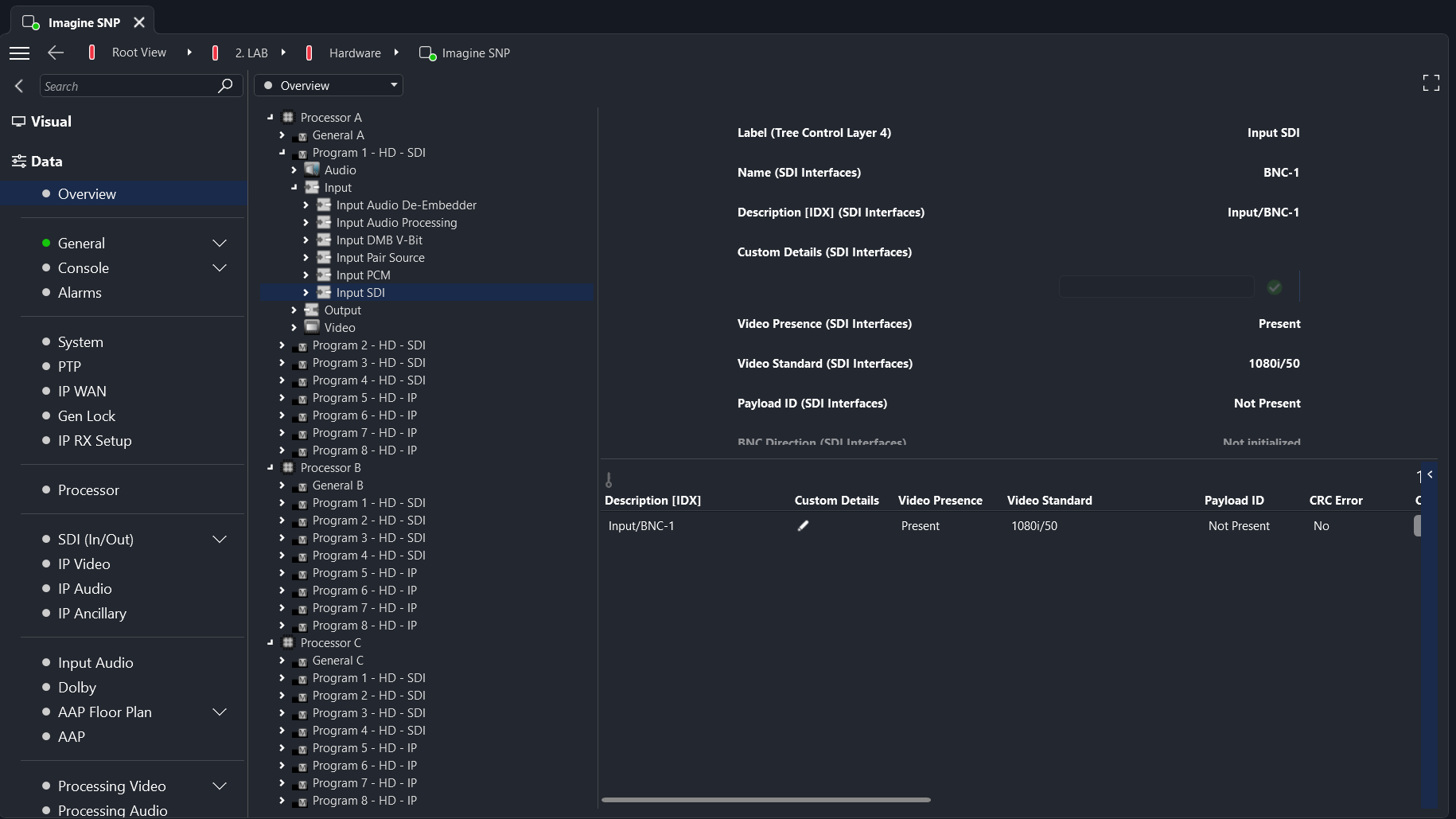
This integration allows you to monitor and control Imagine Communications Selenio Network Processor (SNP) devices.
Key Features
Monitor signal quality in real time: Gain comprehensive visibility into video, audio, and metadata streams with instant detection of issues to ensure seamless content delivery across your entire infrastructure.
Control media processing workflows: Manage synchronization, conversion, format processing, and routing operations across four independent processing blocks with precision control and monitoring.
Support hybrid SDI and IP environments: Seamlessly bridge traditional SDI equipment to ST 2110 IP networks, enabling smooth migration to IP infrastructure at your own pace.
Monitor UHD and HDR content: Track ultra-high-definition and high dynamic range content delivery with support for both HD and UHD operation modes across all processing blocks.
Manage multiviewer operations: Configure and monitor multiple video sources simultaneously with ultra-low latency in both SDI and IP environments for comprehensive signal oversight.
Use Cases
Modernize your broadcast infrastructure with confidence: Transitioning from traditional SDI to IP-based workflows while maintaining operational continuity can be complex and risky. Organizations need a reliable way to monitor and control their infrastructure during this critical migration.
Solution: Deploy DataMiner monitoring for your SNP devices to gain real-time visibility into all processing operations, signal quality, and system health across your entire infrastructure transformation.
Benefit: Maintain complete operational control and instant issue detection throughout your SDI-to-IP migration, ensuring broadcast quality is never compromised while gaining the flexibility and efficiency of modern IP workflows.
Technical Reference
Prerequisites
HTTPS connectivity: DataMiner requires network access to the SNP Manager via HTTPS (default port 9089) to establish API communication. The IP address needs to be preceded by
https://(e.g., enter the IP "192.168.0.1" ashttps://192.168.0.1).Web Socket connectivity (version 1.0.7.1 and above): The SNP uses Web Socket connections (port 9089) for real-time status and configuration updates.
Serial connection (versions before 1.0.7.1): Earlier versions of this connector use a serial connection (port 4517) for real-time status and configuration updates.
Valid credentials: User authentication credentials are required to connect to the SNP Manager for monitoring and control operations. The username and password can be specified on the Security page.
SNP Manager access: The SNP must be managed by an SNP Manager system to enable API communication and remote monitoring capabilities.