SCTE UPS Manager
The SCTE UPS Manager is an application designed to work with power supplies that comply with the SCTE standard communication protocol for transponders. It serves as the main point of administration for the SCTE UPS Collector elements that are in charge of the polling and monitoring of these elements, represented by SCTE UPS DVEs.
It is also possible to group and analyze the traps that the DMA receives from these UPS devices to either provision (i.e., create) a new element or to update some values inside an existing element. For this provisioning and update process, the SCTE UPS Manager has to work in tandem with the SCTE UPS Collectors. This process can be either manual or automatic, according to preference.
About
Version Info
| Range | Key Features | Based on | System Impact |
|---|---|---|---|
| 2.0.0.x [SLC Main] | Automatic and manual provisioning of UPS devices | - | - |
Product Info
| Range | Supported Firmware |
|---|---|
| 2.0.0.x | N/A |
System Info
| Range | DCF Integration | Cassandra Compliant | Linked Components | Exported Components |
|---|---|---|---|---|
| 2.0.0.x | No | Yes | - | - |
Configuration
Connections
SNMP Main Connection
This connector uses a Simple Network Management Protocol (SNMP) connection and requires the following input during element creation:
SNMP CONNECTION:
- IP address/host: The polling IP or URL of the destination.
- IP port: The IP port of the destination.
SNMP Settings:
- Get community string: The community string used when reading values from the device (default: public).
- Set community string: The community string used when setting values on the device (default: private).
How to use
General page
This page allows you to enable or disable automatic provisioning of the detected UPS devices.
The automatic provisioning process consists of the following steps:
The SCTE UPS Manager element receives a Warm or Cold Trap from a UPS device. The trap is registered in the Traps Table.
The manager processes the Traps Table (every 30 seconds) to verify if the device that sent the trap is responding to SNMP requests.
If the device responds to the SNMP requests, the manager verifies if the device has already been provisioned in a SCTE UPS Collector.
- If the UPS device has already been provisioned, the manager verifies if the IP address has changed, and modifies it if necessary.
- If the UPS device does not exist, it will be provisioned in the next available SCTE UPS Collector.
Points to consider:
- The SCTE UPS Manager will choose the next SCTE UPS Collector element with available slots and add the UPS element with the specified name and parameters (maximum 250 UPS devices per element).
- If no more slots are available on any of the SCTE UPS Collector elements, an error will be registered in the Detected Devices Table.
- The automatic process does not allow you to select the order in which the collectors are used. It will take the first available SCTE UPS Collector and start adding SCTE UPS devices to it until no more slots are available. This has been designed this way to ensure the smoothness and reliability of the process.
- The UPS element (DVE) will be located in a view named Pending for allocation. This view must be created by the user.
The manual provisioning process consists of the following steps:
The SCTE UPS Manager element receives a Warm or Cold Trap from a UPS device. The trap is registered in the Traps Table.
The manager processes the Traps Table (every 30 seconds) to verify if the device that sent the trap is responding to SNMP requests.
If the device responds to the SNMP requests, the manager verifies if the device has already been provisioned in a SCTE UPS Collector.
- If the UPS device has already been provisioned, the manager verifies if the IP address has changed, and modifies it if necessary.
- If the device is new, an entry is created in the Detected Devices Table. From this table, you can manually provision the UPS device (see Detected Devices section below).
Points to consider:
- The SCTE UPS Manager allows you to choose one of the detected devices and to configure all its available parameters, starting with the SCTE UPS Collector element in which the SCTE UPS will be monitored and controlled, up to the Name, View, and Properties of the element.
- The user is responsible for distributing the UPS devices over the available SCTE UPS Collectors, with a maximum number of devices per collector of 250.
The General page also contains the Import and Export Provisioning buttons. When you click the Export button, each SCTE UPS Collector element will create a CSV file listing its provisioned DVE devices with their respective information. You can then edit these CSV files and import them together using the Import button.
This page also allows you to import and export the advanced configuration of the UPS devices. When you click the Export button, each SCTE UPS Collector element will create a CSV file with the Element Description, Alarm Template and Trend Template of the UPS devices assigned to it. You can then modify these files and import them together using the Import button.
In the Provisioning Log, you can see the results of the previous import and export actions. The files are located in the SCTE UPS Manager folder within the DataMiner Documents folder.
Finally, the General page also allows you to access the thread information of the element.
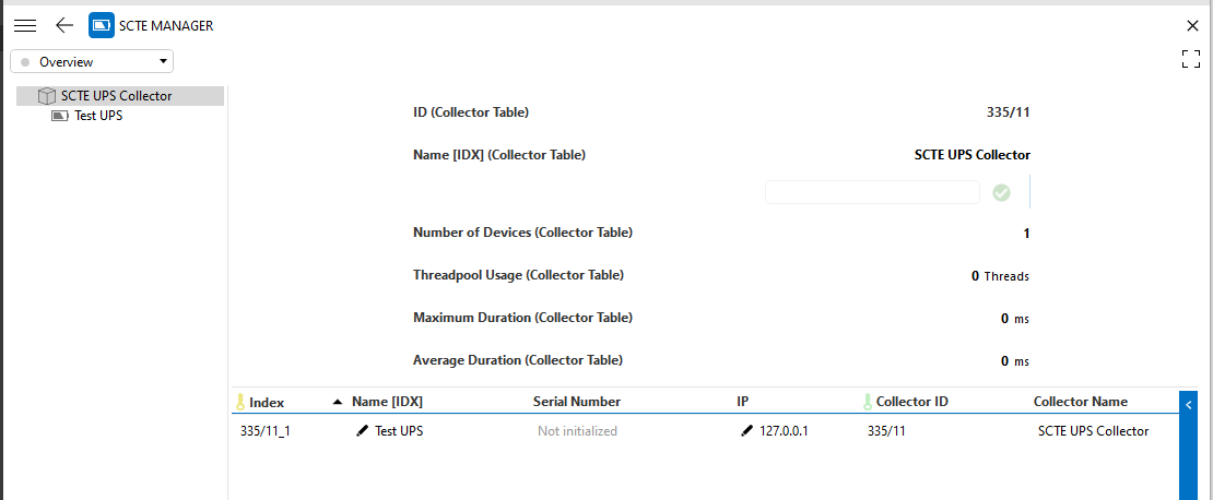
Overview
This page displays a tree view of the available SCTE UPS Collectors and the corresponding provisioned devices.
For each selected SCTE UPS Collector element, basic identification data is displayed, as well as the DVEs that the SCTE UPS Collector has in its devices table.
Collectors
This page displays the Collector Table, which contains the information of all the available SCTE UPS Collectors within the DataMiner System, such as the number of devices per collector and the corresponding thread information.
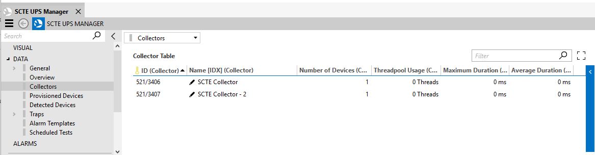
It is possible to modify the Name of the collector elements in this table.
Provisioned Devices
This page contains the Provisioned Devices table, which displays the devices that are provisioned in the available SCTE UPS Collectors. In this table, you can modify the Name and the IP Address of the UPS devices.
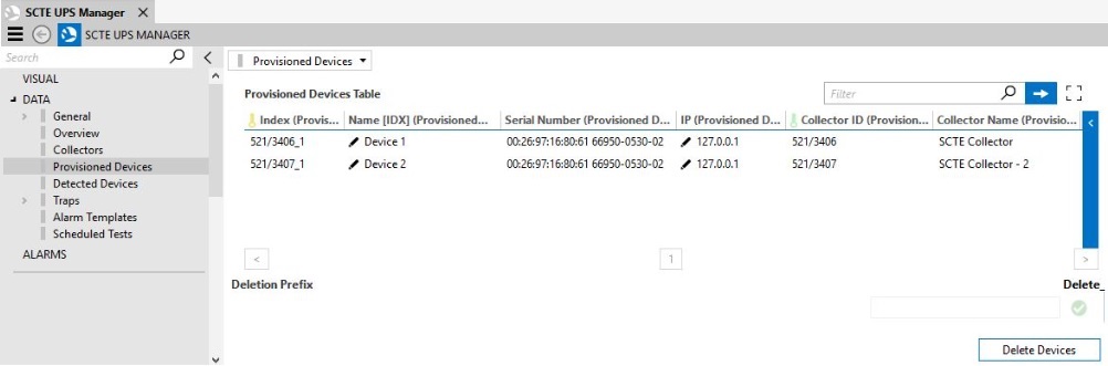
Below the table, a Deletion Prefix can be defined. If the name of a UPS device has this prefix, it will be deleted when the Delete Devices button is pressed.
Detected Devices
The SCTE UPS Manager is capable of detecting Warm and Cold Traps sent by UPS devices (see Traps). With this information, the manager verifies if these devices have already been provisioned in a collector (based on the serial number).
If a device has already been provisioned, the manager will verify if the IP address is still the same and update it in case it is not the same.
If a device has not been provisioned, the manager will determine if Automatic Provisioning is enabled or disabled:
If Automatic Provisioning is Disabled, an entry will be created in the Detected Devices table.
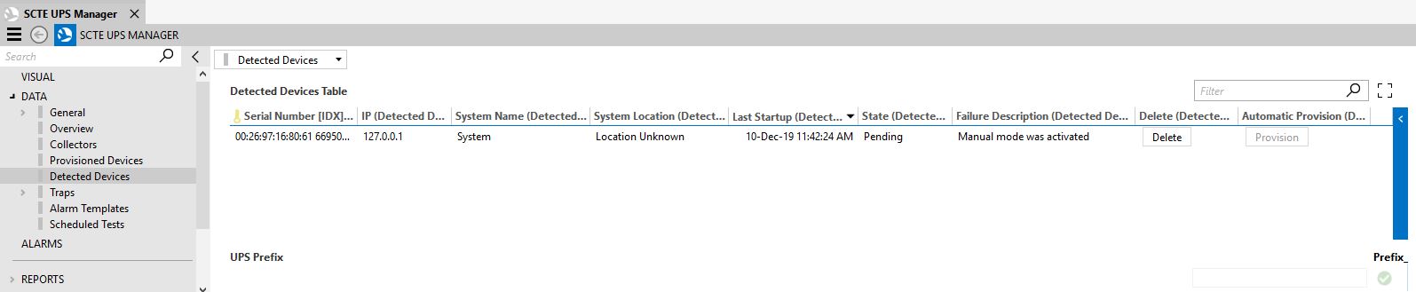
This table displays basic information about the detected device, such as the System Name, System Location, Serial Number and the reason why the device was not automatically provisioned (e.g., because Manual mode was active, like in the image above).
You can manually provision the devices in this table by right-clicking a specific entry and selecting Provision. A pop-up window will then be displayed where you can fill in the basic information of the device. The DMS View and Collector must always be specified.
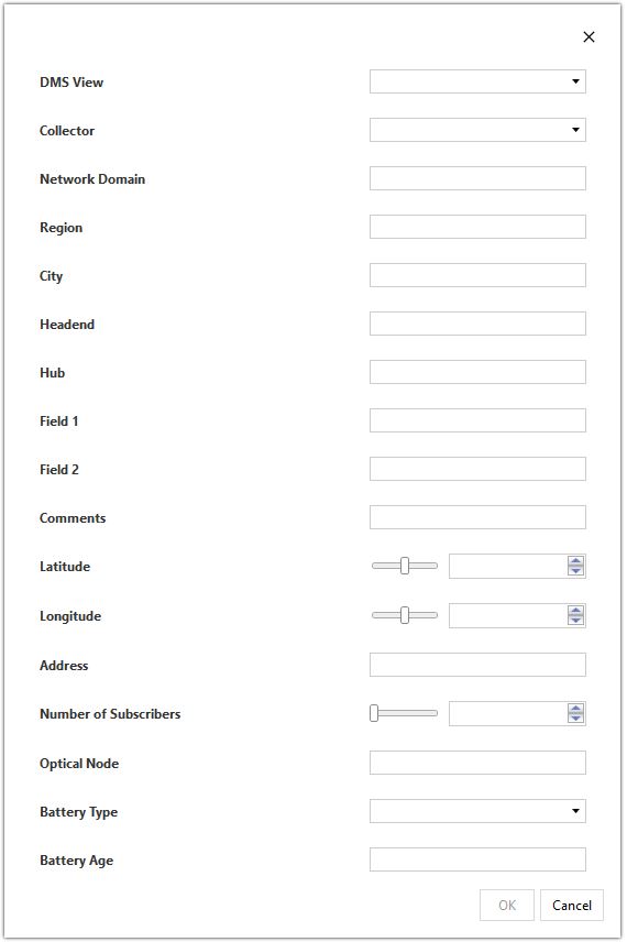
When you click OK, the manager will provision the device in the selected collector. If an error occurs during this process, the details will appear in the Failure Description of the corresponding entry in the table.
When Automatic Provisioning is Enabled, the manager will provision the device in an available SCTE UPS Collector element (taking into account the maximum of 250 UPS devices per collector). If an error occurs during this process, an entry will be created in the Detected Devices table with the corresponding error in the Failure Description.
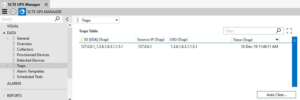
Traps
This page contains the Traps Table, which displays the received Cold and Warm Traps that have not been processed yet. These traps are processed with the help of multithreaded logic. The thread statistics can be found on the General page.
In order for a trap to be processed and removed from the table, the device must respond to SNMP requests.
The subpage Auto Clear is available via a page button on this page. On this subpage, you can configure the maximum number and age of the traps available in the Traps Table.
Alarm Templates
This page displays the Alarm Template Table, where you can configure the parameters that determine which alarm template must be assigned to the UPS devices that are automatically provisioned.
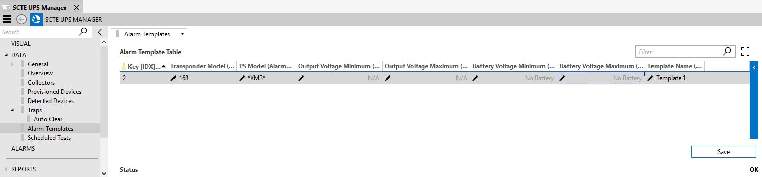
To create an entry in this table, right-click the table and select Add. In the pop-up window, you will be able to configure the alarm template parameters.
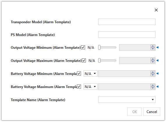
When you have specified the configuration parameters, click Save.
Scheduled Tests (connector version < 2.0.0.12)
This page contains the Scheduled Test table.
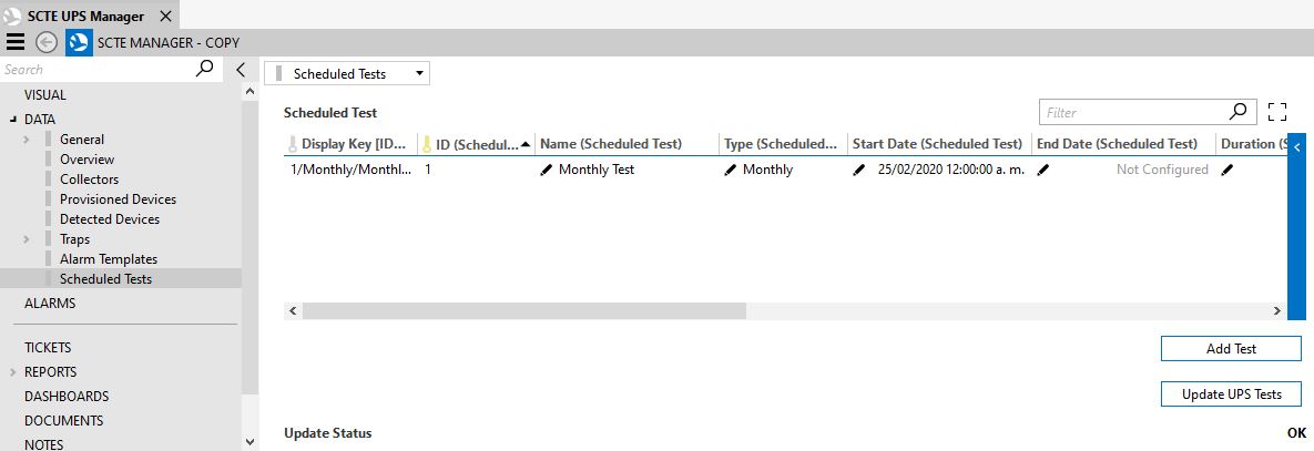
In this table, you can configure the tests that will be created in bulk in all the SCTE UPS Collector elements. To do so, follow the steps below.
Click the Add button at the bottom of the page. An entry will be created in the Scheduled Test Table.
Define a unique Name for the test (mandatory), and then define the type of test (Yearly/Monthly/One Time).
When you have selected the type of test, the entry will be filled in with default values for Start Time, Duration, Minimum Voltage Threshold, and Maximum Voltage Difference, but you can fine-tune these if necessary. You can also define if the test must take into account the Minimum Voltage Threshold or the Full Drain Minimum Voltage Threshold. These are mutually exclusive, so only one can be selected)
You also need to define the End Date, which determines until when the test will be valid. If the test is of type One Time, the end date should be Not Configured.
Configure the Automatic Provisioning. If this is enabled, the test will be created in the automatically provisioned UPS.
Click the button Update UPS Tests. This will replicate the tests in all the available UPS elements. The following logic will be applied in order to avoid all tests getting executed at the same time:
- If a test is of type One Time, the Start Date of the replicated tests in the collectors will be spread out over the 7 days following the configured date in the manager.
- If a test is of type Monthly, the Start Date of the replicated tests in the collectors will be spread out over the 30 days following the configured date in the manager.
- If a test is of type Yearly, the Start Date of the replicated tests in the collectors will be spread out over the 365 days following the configured date in the manager.
Scheduled Tests (connector version >= 2.0.0.12)
In version 2.0.0.12 of the connector, the Scheduler module is integrated with the UPS tests. As a consequence, the test creation procedure is different:
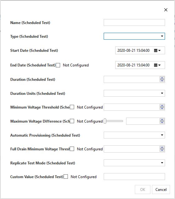
Right-click the Scheduled Test table and select Add. A pop-up window will be displayed where you can fill in the test information.
Define a unique Name for the test (mandatory), and then define the type of test (Yearly/Monthly/One Time).
Define the Start and End Date of the test. If the test is Yearly or Monthly, the End Date is mandatory; if the type is One Time, set the End Date to Not Configured.
Set the Duration, Duration Unit and Maximum Voltage Difference. You can also define if the test must take into account the Minimum Voltage Threshold or the Full Drain Minimum Voltage Threshold. These are mutually exclusive, so only one can be selected.
Configure the Automatic Provisioning. If this is enabled, the test will be created in the automatically provisioned UPS. Take into account that tests with Replicate Mode set to Custom Group cannot have this option enabled.
Configure the Replicate Test Mode and Custom Value.
From version 2.0.0.12 of the connector onwards, the test replication feature is available, so you can also select where the tests should be replicated:
- All Collectors: The test is applied to all UPS elements. Set the Replicate Test Mode to All Collectors and the Custom Value to Not Configured.
- Custom View: The test is applied to the UPS elements that are located in a specific view. Set the Replicate Test Mode to Custom View and the Custom Value to the name of the view.
- Custom Group: The test is applied to the UPS elements that are part of a specific group. Set the Replicate Test Mode to Custom Group and the Custom Value to the name of the group. (The group configuration is done in the SCTE UPS Collector elements).
Click OK.
Once all the tests have been created, click Update UPS Tests. This will replicate the tests in all the available UPS elements. The following logic will be applied in order to avoid all tests getting executed at the same time:
- If a test is of type One Time, the Start Date of the replicated tests in the collectors will be spread out over the 7 days following the configured date in the manager.
- If a test is of type Monthly, the Start Date of the replicated tests in the collectors will be spread out over the 30 days following the configured date in the manager.
- If a test is of type Yearly, the Start Date of the replicated tests in the collectors will be spread out over the 365 days following the configured date in the manager.
The button Sync Tests is also available from version 2.0.0.12 onwards. It can be used to integrate tests that were created with connector versions lower than 2.0.0.12 of the SCTE UPS Manager and 1.0.2.21 of the SCTE UPS Collector in the Schedule module of DataMiner. This action should only be performed once.