Skyline ICMP Platform Manager
About
This connector is part of a generic solution that monitors the connection health of several ICMP-capable devices via ping and aggregates the results to provide an overview at different levels.
The Skyline ICMP Platform Manager element can be configured in two ways:
Frontend: The frontend element acts as the main entry point to the solution. It will gather all information from the backend and the collector elements to calculate the KPI. Only one frontend element should be created for the solution.
Backend: A backend element is responsible for the aggregation of the data from the collector elements. It is possible to have more than one backend element integrated in the system. We suggest that you create one per DMA.
Different search topologies are presented in the Skyline ICMP Platform Manager. These topologies are diagrams shown in Visual Overview that describe the logical connections between the entities of the infrastructure. The current implementation integrates the following topologies: Location, State, Model, Station, and Quick. Each topology represents a connected entity from top to bottom. The following chains are present:
Location:
- Super-Region
- Sub-Region
- State
- City
- Device
State:
- State
- Device
Model:
- Model
- Device
Station:
- Station
- Device
Quick: This allows you to quickly access the topology level by selecting the desired filter (Super-Region, Sub-Region, State, City, Model, Station, Device).
Configuration
Configuration
Connections
Virtual Connection
This connector uses a virtual connection and does not require any input during element creation.
Initialization
To configure the entire system properly, as a DataMiner System Administrator, you should follow these steps:
Create a frontend Skyline ICMP Platform Manager element by setting the parameter Element Manager Type to Front-End on the Configuration page.
Create one or more backend Skyline ICMP Platform Manager elements by setting this same parameter to Back-End on their Configuration page.
Create a Collector element.
Define the File Import and Export Path on the Configuration page. If you change the default path, keep in mind that the same configuration needs to be executed on all the ICMP elements in the system.
- If the File Import Path or File Export Path is in a remote location, fill in the Username and Password fields in the System Credentials section of the Configuration page.
Register the Collector element (DMA ID/element ID) in the Collector Registration table on the Front-End or Back-End page.
If you are configuring the frontend, register the backend (DMA ID/element ID) in the FE-BE Registration table; otherwise register the frontend.
In the location specified in the File Import Path parameter earlier, provide a CSV file (separated by ";") with the format illustrated below.
If the folder defined in the parameter does not exist, you will need to create it.
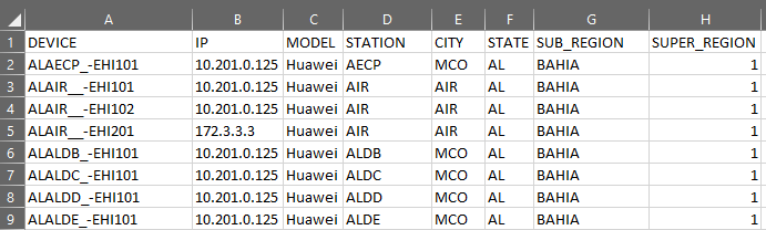
Note that headers must be capitalized, and the file name should follow the format DMAID_ElementID_ICMP.
The relation in the CSV file between topology levels must be One-to-Many from up to down and One-to-One from down to up. Levels from up to down: Super-Region, Sub-Region, State, Station, Model, and Device.
Redundancy
There is no redundancy defined.
How to use
When the initialization steps have been completed, go to the Configuration page of the frontend element, and click the Import button to load the information of the provided CSV file. This action will create a CSV file with the IDs for every entry to be read by the backend element and a Device_Config.json file with those generated IDs.
Then click the Import button in the backend element to generate the CSV file that the collector needs to fill all its tables.