Tektronix SignalVu
The Tektronix SignalVu is a spectrum connector that polls and displays the real-time trace. Different display options can be configured, such as Start/Stop Frequency, Amplitude Scale and Reference Scale.
About
The connector communicates through a VISA interface, using the GPIB protocol.
Version Info
| Range | Description | DCF Integration | Cassandra Compliant |
|---|---|---|---|
| 1.0.0.x | Initial version. | No | Yes |
Product Info
| Range | Supported Firmware Version |
|---|---|
| 1.0.0.x | Unknown |
Prerequisites
Due to the nature of this device, several packages need to be installed and configured on both the remote system and the DataMiner server. These packages contain third-party software. Skyline communications is not responsible for the correct operation and performance of the packages.
DataMiner Server
- Go to the National Instruments download page (http://www.ni.com/es-co/support/downloads/drivers/download.ni-visa.html) and select the most recent version of the Ni-VISA suite. Please ensure that the package is not the Run-Time Engine.
- Once you have downloaded the package, copy the installer to a folder on the DataMiner server.
- Follow the steps recommended from National Instruments.
- Restart the server.
Remote System
Install Tektronix SignalVU as recommended by Tektronix.
Ensure that the spectrum analyzer is connected on a USB 3.0 port.
Go to the Tektronix TekVISA connectivity software page (https://www.tek.com/oscilloscope/tds7054-software/tekvisa-connectivity-software-v411) and download the file.
Install the package according to the instructions from Tektronix.
Restart the computer.
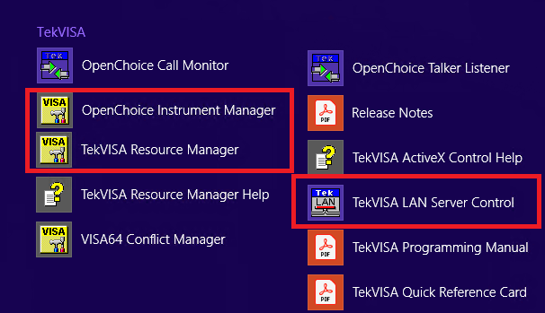
You should see the following applications (the ones marked with a red box are the ones we will use):
Installation and configuration
For this system to be accessed from the DataMiner server, some configuration is necessary of the Tektronix TekVISA tools as well as the National Instruments NiVisa package. The following are the most common steps that you should follow in order to ensure correct communication between the two systems. If you need additional technical information on how these tools work or if you want to report a bug related to them, please contact Tektronix or National Instruments directly.
Remote System
Open the TekVisa Resource Manager.
There you should see a GPIB interface under Instruments. It should be something like this:
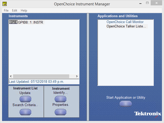
If there is no GPIB present, go to the SignalVU User Manual and follow the Troubleshooting guide.
Open the TekVisa LAN Server control application.
This application does not run in a normal window. To see if it is running, go to the taskbar (near the clock) and right-click the TekVISA icon.
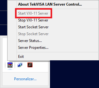
Click Start VXI-11 Server (option surrounded by the red square in the image above).
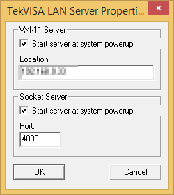
Click Server Properties and ensure that both options are set to start when Windows starts, as illustrated below.
Hover the mouse over the TekVisa LAN Server icon to check if you see an IP address (the same as your computer).
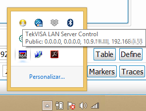
This indicates that the server is ready to pass the packets to the SignalVU Virtual GPIB. You can find more technical information on the Tektronix home page or in the SignalVu User Manual.
Restart your computer to ensure that all services are active.
DataMiner Server
On the DataMiner server, the National Instruments NiVISA package must be configured. This will allow the Tektronix SignalVu driver to communicate with the computer.
Open the NiMax application that was previously installed on the server.
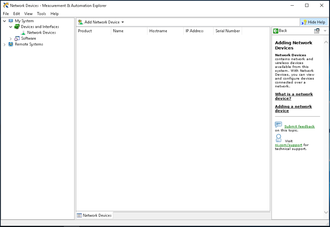
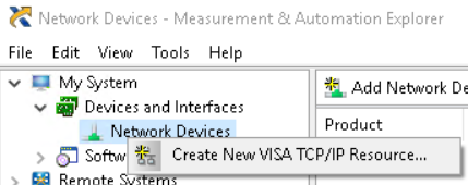
In the tree view on the left, go to Devices and Interfaces > Network Devices.
Right-click Network Devices and select Create New VISA TCP/IP Resource.
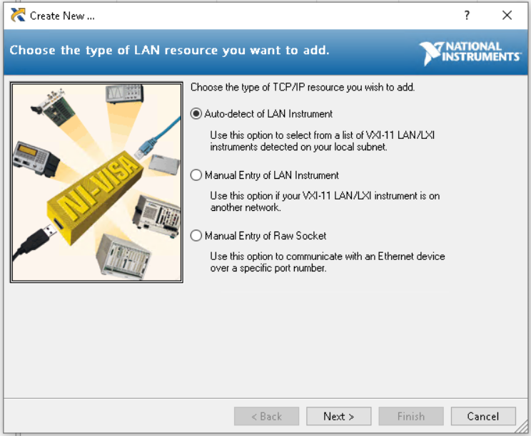
A new window will open with several options.
In the new window, select Auto-Detect of LAN Instrument and click Next.
Select Select intrument(s) detected on local subnet.
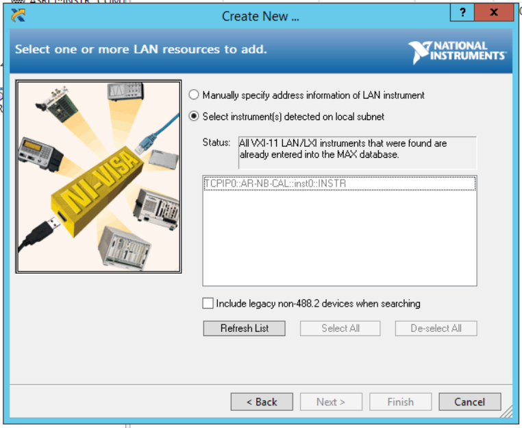
When all results are displayed in the box below, select the desired device.
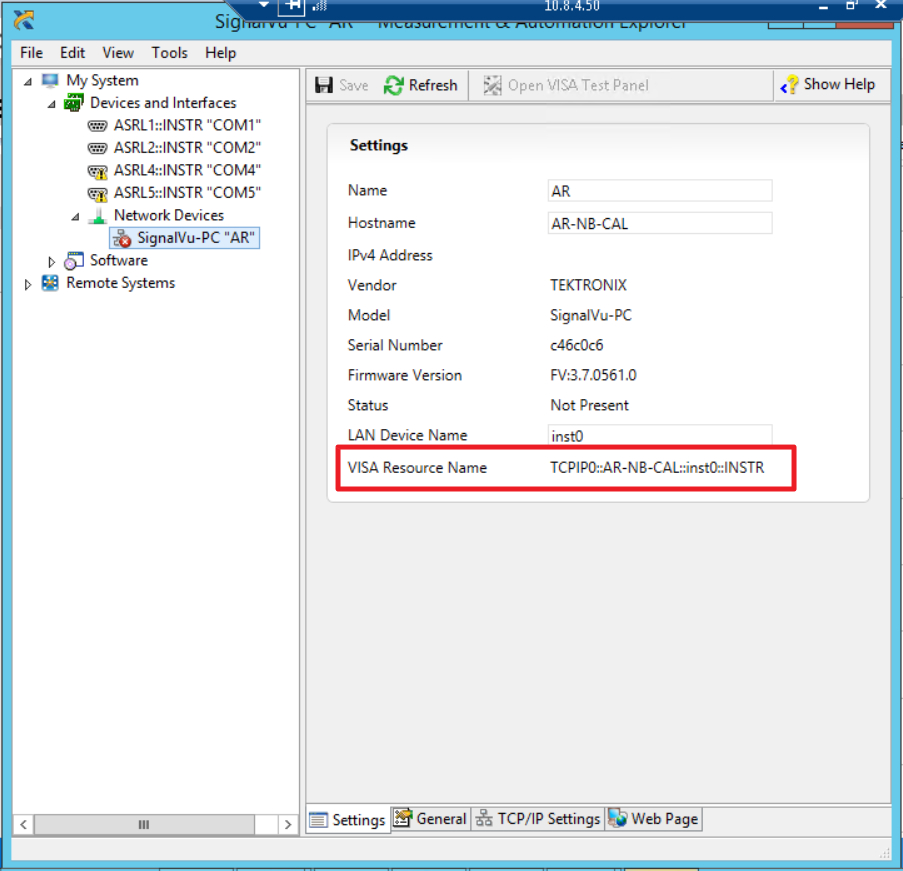
Note down the displayed address, as you will need it during the DataMiner element creation.
Click Finish.
The options tree will be updated and a LAN device will be created.
Close the window.
Element creation in DataMiner
GPIB Main Connection
This connector uses a GPIB connection. Before starting element creation, you should have the following information available:
GPIB connection:
- Device address: This is the address you had to note down when the Visa Network creation process ended. It was displayed at the end of the wizard. The parameter inside NiMax is called VISA Resource Name.
- I/O API: The I/O API to use for the GPIB connection. For better compatibility with the previous configuration, please select VISA.
Usage
Spectrum Analyzer
This element uses the DataMiner Spectrum Analysis interface. For more information on the basic and advanced features of this interface, please refer to DataMiner TV: https://dataminer.tv/Video?q=spectrum
Before you first use the spectrum analyzer, please note the following differences with regular spectrum analyzers that apply for the SignalVU interface:
On the Spectrum Analyzer page, you can modify all parameters explained in the DataMiner TV videos. However, you can only change one of the following at a time:
- Start and Stop frequency
- Frequency span and Center frequency.
If you try to modify both at the same time, the device will not support this and erratic measurements could be generated.
This device does not support any commands to set the sweep time, as this is calculated internally taking into account the frequencies used (or the span) and the RBW.
Therefore, the sweep time can only be configured in DataMiner for local use. If an incorrect value is set, it may cause an incomplete trace to be generated.
General
This page displays the Manufacturer, Model Number, Serial Number and Firmware Package Number. The Acquire Mode is also displayed, which can be Continuous or Single.