Below you can find a categorized list of the connectors supported by range 5.0.0.x that will be used for creation of new elements.
This connector uses a serial connection and requires the following input during element creation:
This connector uses a serial connection and requires the following input during element creation:
Depending on the range of connector that is being used, different features are available. You can find more information about this below.
Range 5.0.0.x of the Teleste HDC100 connector does not create DVE elements but new elements that use their own connector depending on the node model.
General Page
This page displays general information such as the Alias Name and Location. It also contains general hardware and software info and statistics such as uptime, total uptime, reset count, and position.
Monitoring Page
This page contains two tables, one for analog and one for discrete alarm limits. Both tables provide detailed information about each alarm and allow you to configure the read/write parameters for each alarm.
Module Overview Page
This is the main page for all devices connected to the controller. It contains parameters for easier control over created elements. This includes counters indicating the total number of elements connected to the controller, as well as a table with details about the connected nodes.
You can configure automatic removal of missing nodes, creation of elements with invalid submasks, and creation of elements that are not in the config file.
The page has two subpages:
Configuration: This page allows you to select a specific .csv file to use for the configuration of the elements. The config files must be located in the following directory: C:\Skyline DataMiner\Documents\Teleste HDC100 TSEMP\.
Template: This page shows the alarm and trend templates for each supported connector available in your DMS.
Note
For each connector, one default alarm or trend template can be selected.
Interfaces Page
On the Interfaces page, a table with two rows provides an easy overview of the information related to Ethernet and the HDO bus. It includes all information regarding communication such as the IP address, net masks, gateway address, mastering mode, master address, poll timeout, packet timeout, etc.

Note
For some cells, it is not possible to set values. In the logging for the element, you can see notifications for commands that are not supported.
Detailed logging about polled modules
Detailed logging about polled modules is disabled by default on app level. To enable this, enable the parameter Debug Logging State (ID 5).
Supported Modules
Below you can find a comprehensive overview of the exported connectors used for the creation of DVEs.
Transmitters
| Supported Connector |
Description |
| Teleste HDC100 TSEMP - HDO302 |
DFB laser transmitter. |
| Teleste HDC100 TSEMP - HDO371 |
DWDM DFB laser transmitter. |
| Teleste HDC100 TSEMP - HDO773 |
1550 nm DWDM transmitter. |
| Teleste HDC100 TSEMP - HDO775 |
Downstream transmitter. 1550 nm DWDM transmitter for short, medium, and long distances. |
| Teleste HDC100 TSEMP - HDO902 |
1310 nm DFB transmitter for forward path fiber-optic links in CATV networks. |
| Teleste HDC100 TSEMP - HDO904 |
O-band DWDM laser transmitter for forward path fiber-optic links in CATV networks. |
| Teleste HDC100 TSEMP - HDO905 |
Linear directly modulated DFB laser transmitter for forward path fiber-optic links in CATV and FTTx networks. |
| Teleste HDC100 TSEMP - HDO906 |
Directly modulated linear O-band DWDM DFB laser transmitter for forward path fiber-optic links in CATV and FTTx networks. |
Amplifiers
| Supported Connector |
Description |
| Teleste HDC100 TSEMP - HDO421 |
Return path amplifier with 20 dB gain. |
| Teleste HDC100 TSEMP - HDO610 |
Forward path amplifier with four outputs and 10 dB gain. |
| Teleste HDC100 TSEMP - HDO611 |
Output forward amplifier with 16 dB or 21 dB gain and optional spectrum analyzer. |
| Teleste HDC100 TSEMP - HDO613 |
Forward path amplifier. |
Receivers
| Supported Connector |
Description |
| Teleste HDC100 TSEMP - HDO202 |
Dual receiver with frequency range 5-300 MHz and output switches for return path fiber-optic links in CATV networks. |
| Teleste HDC100 TSEMP - HDO203 |
Dual receiver for return path (upstream) fiber-optic links. |
| Teleste HDC100 TSEMP - HDO204 |
Quadruple receiver module with 230 MHz and DOCSIS 3.1 compatibility for fiber-optic return path links in CATV networks. |
| Teleste HDC100 TSEMP - HDO212 (3.1.0.x) |
Dual receiver module for fiber-optic return path links in CATV networks. |
| Teleste HDC100 TSEMP - HDO802 |
Optical forward path receiver. |
Power Supplies
| Supported Connector |
Description |
| Teleste HDC100 TSEMP - HDP230 |
Switching mode power supply with load sharing functionality. |
| Teleste HDC100 TSEMP - HDP301 |
Switching mode power supply with load sharing functionality. |
Other Modules
| Supported Connector |
Description |
| Teleste HDC100 TSEMP - HDO101 |
RF switch module used for signal backup purposes. |
General Page
This page displays the general parameters of the device, such as the Alias Name, HW Version, SW Version, BIOS Version, Up Time, Rack Number, and Temperature.
It contains three page buttons:
Ping: Displays parameters that allow you to configure the ping execution: Execution Time, Result, Mean RTT, State, Number, Cycle, Timeout.
Network: Allows you to configure the IP Address, Network Mask, Default Gateway, Mastering, Poll and Packet Timeout, and Master Address, as well as the HDO parameters IP Address, Network Mask, and Default Gateway.
Monitoring: Contains both the Analog and Discrete Alarm Limits Tables, as well as the parameters Alarm Control Detection, ACD on Delay, and ACD off Delay.
In the Analog Alarm Limits Table, the HiHi, Hi, LoLo, Lo, Deadband, HiHi State, Hi State, Lo State, and LoLo State can be configured.
For the Discrete Alarm Limits, the settings can be configured, and the alarm status can be monitored.
Overview Page
This page contains the Modules Table. A DVE will be created for each of the cards listed in this table that have their Status set to OK.
The page also allows you to enable or disable the Automatic Removal of missing modules. In addition, it displays the Number of Devices in the table, which can be updated with a Refresh button.
The Configuration page button provides access to a subpage with the following settings:
- Timer Configuration: Allows you to configure the polling time, using the following parameters: Fast Timer Interval, Medium Timer Interval, and Slow Timer Interval.
- DVE Settings: Allows you to enable or disable Element Prefix, Automatic DVE Name, and Automatic DVE View. There is also an option to Delete Hanging DVEs, which can be of use when a module is swapped with a module of a different type in the same position.
- Configuration Import: Allows you to specify a custom Configuration Directory (the default directory is
C:\Skyline DataMiner\Documents\Teleste HDC100 TSEMP). Via the Configuration File dropdown menu, you can select one of the configuration files present in the directory. With the Import button you can then import the file. The Refresh button allows you to refresh the dropdown menu.
HDO101 / HDO202 / HDO204 / HDO302 / HDO371 / HDO421 / HDO610 / HDO611 / HDO613 / HDO773/ HDO775 / HDO802 / HDO902 / HDO904 / HDO905 / HDO906 / HDP230 / HDO231 / HDO908 Pages
Each of these pages displays a table specific to the module in question, an Analog Alarm Limits table, and a Discrete Alarm Limits table.
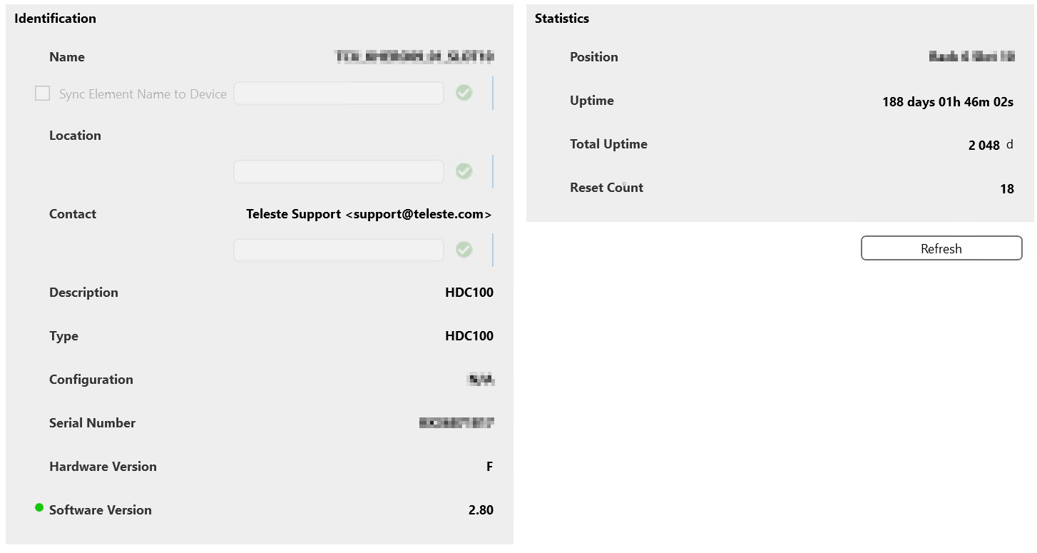
General Page
This page contains identification information and statistics for the device, as well as a Reset Device button.
The identification information includes the general parameters for the HDC100 device, such as its Name (configurable), Type, Configuration, Software Version, BIOS Version, Hardware Version, Rack and Slot Number, etc.
The statistics include the Uptime, Total Uptime, Number of Restarts, Temperature, and Alarm Control Detection. This section also contains a button that provides access to a subpage with the Analog and Discrete Alarm Limits Table.
Interfaces Page
This page contains network settings such as the IP Address, Network Mask and Default Gateway, as well as the following HDO Bus parameters: IP Address, Network Mask, Default Gateway, Master Address, Mastering, Poll Timeout, and Packet Timeout.
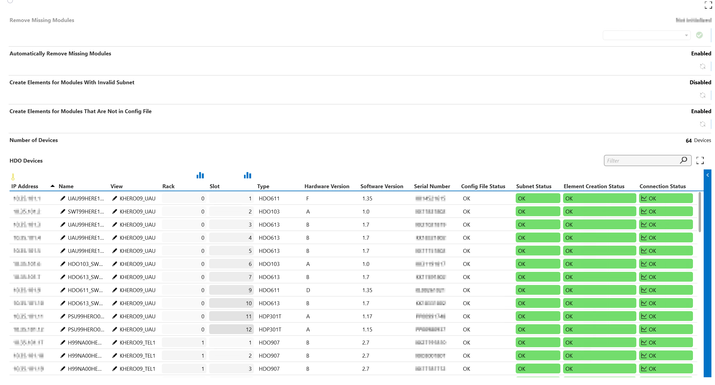
Module Overview Page
This page displays the HDO Devices Table. It also allows you to Remove Missing Modules.
In addition, the Configuration page button provides access to a subpage with:
- The Refresh File List button.
- The possibility to upload a Configuration File.
- The possibility to enable or disable the Automatic View Check.
- The Manual View Check button.
SW Update Page
This page includes the following parameters:
- Load Status
- File Path in order to Load the File
- Update HW_model
- Update HW_Version
- Update Target
- Update Format
- Update Status
- Update Block Number
- Update Message
- Send Update
- Abort Update
DVE Tables Page
All DVE tables for the different modules are present on this page:
- OTX HDO902 DVE Table
- ORX HDO202 DVE Table
- PSU HDP DVE Table
- UAU HDO611 DVE Table
- RFS HDO101 DVE Table
- RAU HDO421 DVE Table
- OTX HDO905 DVE Table
- ORX HDO212 DVE Table
- TRM HDO907 DVE Table
- TRM HDO775 DVE Table
- HDO906 DVE Table
- HDO908 DVE Table
- HDO613 DVE Table
- HDO103 DVE Table
- HDO203 DVE Table
For each of the tables, a subpage allows you to enable or disable the automatic removal of deleted modules or to remove modules manually.
Alarm Limits Pages
These pages display the Analog and Discrete Alarm Limits Table for each of the module types. In the Analog Alarm Limits Table, you can configure the HiHi, Hi, Lo, LoLo, and Deadband, as well as the Status for each of these columns.
General Page
This page displays identification information and statistics for the device.
- Ping: Ping status and settings.
- Network: Network settings of the device and HDO bus.
- Monitoring: Overview of the analog and discrete alarm limits of the device.
Overview Page
For every card type, an entry is created in the Modules table. Different configurations are possible (e.g., Automatic Removal) in order to delete the modules with status Missing.
Configuration
Timer Configuration: The polling of the data for the modules can be configured by setting the different timer intervals.
DVE Settings: Settings to configure the DVEs.
Configuration Import: When Automatic DVE Name is set to Configuration File, the selected configuration file will be used with the DVE name and view that need to be used.
Every line in the CSV file represents a module of which the data should be in the following format: Main Element IP Address;Rack Number;Slot Number;DVE Name;DVE View
Example:
10.3.3.9;0;4;DVE Name 1;DVE View 1
10.3.3.9;0;7;DVE Name 2;DVE View 2
10.3.3.9;1;9;DVE Name 3;DVE View 2
Module Type pages
For every supported module type (exported connector), a page is available with an overview of the Details, Analog Alarm Limits and Discrete Alarm Limits of that module type.