Use case: Internal flow – HTTP connection
By means of a practical example, this page will illustrate the overall concept of the internal flow when an element uses a protocol definition that needs to interact with a data source using an HTTP connection. For more information on how the returned data is processed, see Use case: Internal flow – QActions.
The use case
The example used in this use case is a click on a button to retrieve data.
The protocol definition structure will look like this:
Parameter (button) > Trigger (change) > Action (execute) > Group (session)
Note
Data is returned in the defined response parameter in the session. To process this and for example have it displayed, a QAction is used. For more information on this flow, refer to Use case: Internal flow – QActions.
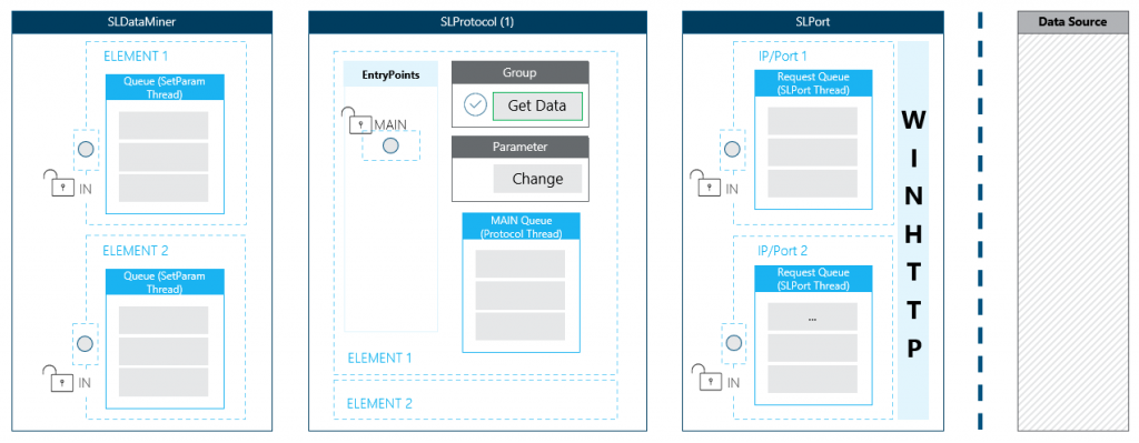
The diagram
The diagram will cover only one SLProtocol process. At runtime, multiple processes will be running, each handling multiple elements.
Note
By default, this is independent of the assigned protocol definition, but it is possible to configure DataMiner to have one SLProtocol process per running protocol definition.
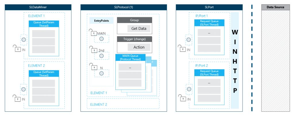
There is always a main entry point available for handling incoming requests from any queue. For any additional connection, an extra entry point is generated. If an incoming request is busy, the entry point will be blocked for any other interactions.
Note that by default, each of these entry points will link to the main queue that is processed via the protocol thread. With an extra feature defined in the protocol definition, it is possible to create extra queues for a specific entry point (connection).
Imagine the protocol definition has two connections defined. By adding the feature below, three queues can be used to process logic in parallel of each other.
<Threads>
    <Thread connection = "0"/> <!--Queue via MAIN EntryPoint-->
    <Thread connection = "1"/> <!--Queue via 2nd EntryPoint-->
    <Thread connection = "1001"/> <!--Extra Queue via MAIN EntryPoint -->
</Threads>
The flow explained
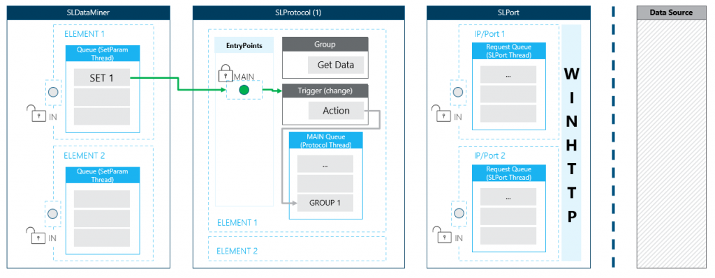
Step 1: Add a group to queue on button click
In this case, data needs to be retrieved from an external source. This means the logic needs to execute a group containing the required information to set up the necessary HTTP communication.
The click of the button will add a parameter SET to the queue of the SetParameter thread. Once this set can be handled, it will trigger a change on the write parameter causing the main entry point to be locked, blocking any other interaction via this point.
The lock will be released as soon as all the logic linked to the parameter change is done. In this use case, the only linked logic is adding a group. So as soon as the group is added to the main queue of the protocol thread, the entry point is available again.
Note
In the diagram, the parameter representation is omitted to keep the overview clean.
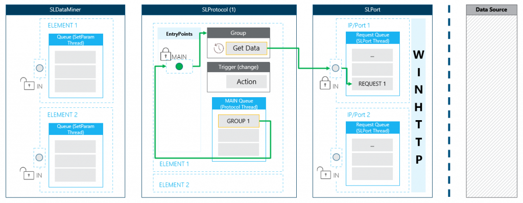
Step 2: The group is executed
Once the group is ready to be executed, the main entry point is locked again.
The content of the group contains a session, and this session holds all the information to interact with the data source.
<Group id="1">
    <Name>getData</Name>
    <Description>Get Data</Description>
    <Type>poll</Type>
    <Content>
        <Session>100</Session>
    </Content>
</Group>
Imagine that a GET request must be executed to retrieve an XML file:
<Session id="1" name="getData">
    <Connection id="1" name="Get Data">
        <Request verb="GET" url="/data.xml">
            <Headers>
                <Header key="Accept">text/xml;charset=UTF-8</Header>
            </Headers>
        </Request>
        <Response statusCode="10">
            <Content pid="20"></Content>
        </Response>
    </Connection>
</Session>
The request will be passed to SLPort where it is added to a queue that handles all the requests for a specific IP and port combination.
Note
It is possible that multiple elements are using the same IP and port. The requests for these elements will then be added to the same queue.
Step 3: WINHTTP handles the request
All HTTP communication is handled via WINHTTP. SLPort will pass all the information required to handle the request, and WINHTTP will handle the rest. Because of this, Stream Viewer might show an error such as WINHTTP_ERROR_TIMEOUT or ERROR_WINHTTP_CANNOT_CONNECT.
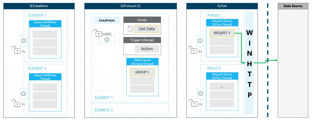
As long as the request is busy, it will remain in the request queue of the SLPort thread, blocking the execution of others for this IP/port combination. A similar situation in the main queue of the SLProtocol thread: the group will block the execution of others until its content and any linked logic is finished.
Since the entry point is open, interaction is still possible. For example, a QAction triggered directly from a set on a parameter can run while the data source is still busy collecting the data.
Step 4: Handling the response
When the data source returns the requested data (handled via WINHTTP), the value is set on the parameter defined in the session response.
For example:
<Session id="1" name="getData">
    <Connection id="1" name="Get Data">
        <Request verb="GET" url="/data.xml">
            <Headers>
                <Header key="Accept">text/xml;charset=UTF-8</Header>
            </Headers>
        </Request>
        <Response statusCode="10">
            <Content pid="20"></Content>
        </Response>
    </Connection>
</Session>
The content of the data file will be stored in the parameter with ID 20.
Similar to the click on the button, the set will pass via the main entry point blocking the interaction.
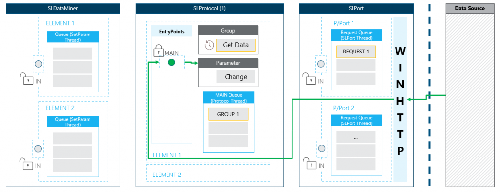
Imagine that this parameter will trigger a QAction to process the data. This means that the QAction must finish before:
- The group will be removed from the main queue of the SLProtocol thread.
- The request will be removed from the request queue of the SLPort thread.
- The main entry point is released.