Use case: Internal flow – concept
By means of a practical example, this page will illustrate the overall concept of the internal flow when running an element using a basic protocol definition. This concept can be applied as a basic structure on any definition.
The use case
The goal of the protocol definition in this example is to send out a GET request to a remote data source whenever a user clicks a button. This could be via SNMP, HTTP, or even serial communication. The button is represented by a SET in the diagrams, as the user will set the button value.
The protocol definition contains a simple logical flow:
Parameter (button) > Trigger (on change) > Action (execute group) > Group (poll data) > Trigger (after group) > do something
At runtime, the user will click the same button twice while at the same time another user clicks (or sets) something else on another element.
The diagram
The diagram will cover only one SLProtocol process. At runtime, multiple processes will be running, each handling multiple elements.
Note
By default, this is independent of the assigned protocol definition, but it is possible to configure DataMiner to have one SLProtocol process per running protocol definition.
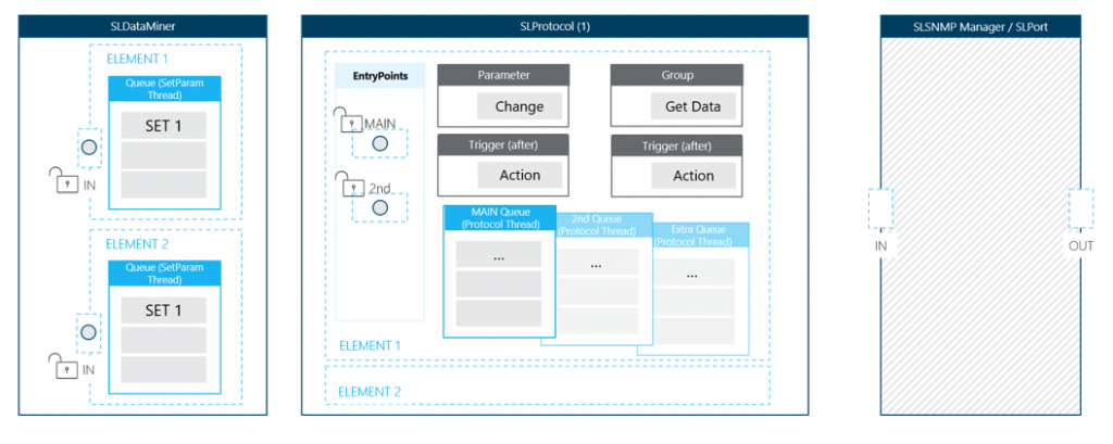
Every protocol has at least one entry point. The number of entry points is defined by the number of connections. These entry points are used to handle requests from ANY type of queue. As an entry point is only capable of handling one request at a time, other requests will have to wait their turn until the entry point is done processing its current request.
Note
By default, each of these entry points will link to the main queue that is processed via the protocol thread. With an extra feature defined in the protocol definition, it is possible to create extra queues for a specific entry point (connection).
Imagine the protocol definition has 2 connections defined. By adding the feature below, three queues can be used to process logic in parallel of each other.
<Threads>
    <Thread connection = "0"/> <!--Queue via MAIN EntryPoint-->
    <Thread connection = "1"/> <!--Queue via 2nd EntryPoint-->
    <Thread connection = "1001"/> <!--Extra Queue via MAIN EntryPoint -->
</Threads>
The flow explained
Step 1: Two users setting a value on different elements
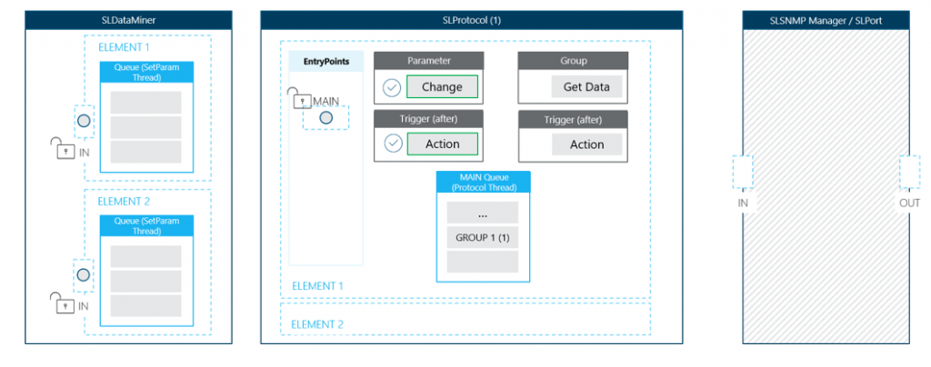
The focus in this diagram is on the SLDataMiner process. This process contains a queue for each element in the DataMiner System. Every queue holds the current parameter sets for their respective element. Each item in this queue will be processed sequentially by the SetParameter thread.
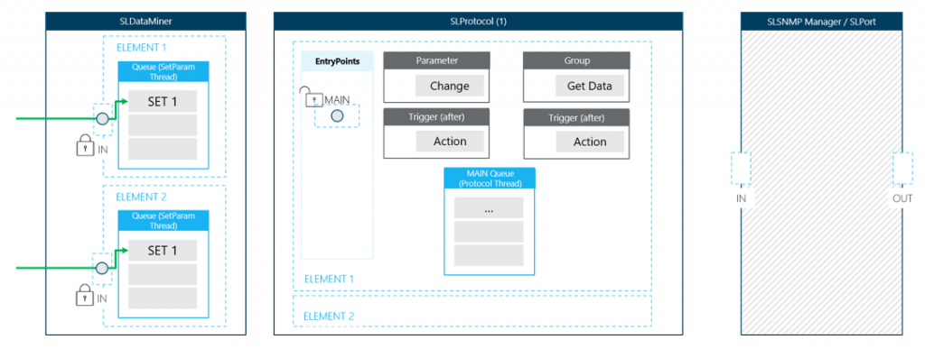
Note
Each element has its own queue. This means that sets on different elements can be executed simultaneously. Sets on different elements are handled independently of one another. Two sets on the same element will be handled one after the other.
Step 2: Set triggers logic
In this use case, the SetParam thread will execute the next SET on the element. It will use the main entry point and as such it will block any other interaction with this element.
The set on the button parameter will execute a trigger (on change) and run an action (execute) that will add a group to the protocol queue.
Note
In case there was a second SET in the queue, it will need to wait until the first SET is handled (see step 5).
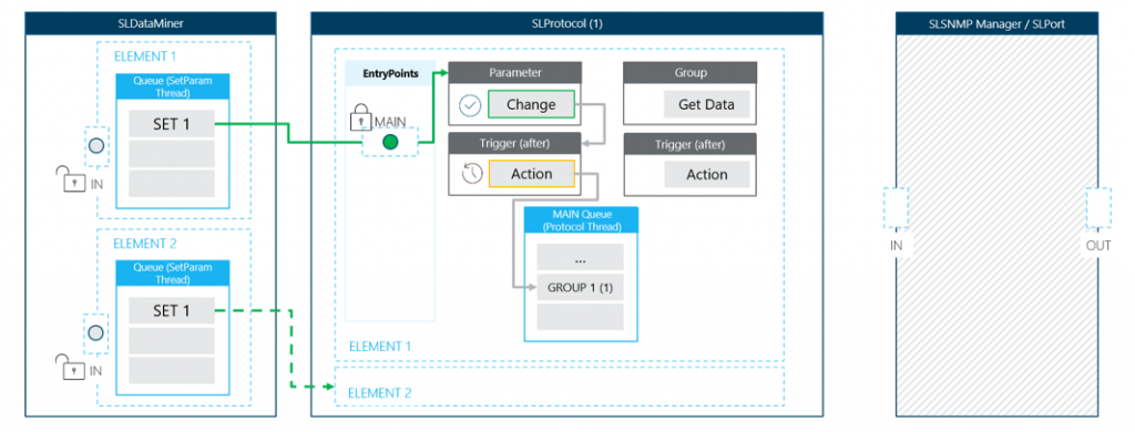
At the same time, the SET on the second element can be processed in a similar way.
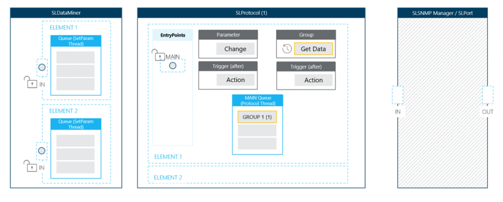
Step 3: Group on the queue (protocol thread)
An action (execute) will move the group to a queue of which every item is processed by the protocol thread. This is similar to adding an item to a to-do list. The item itself is not yet done, but it’s on the list and will be handled sometime in the future.
The action (execute) is now complete; it has added the group to the protocol queue. As there were no other triggers defined on the parameter, the SetParam thread has finished handling the SET from SLDataMiner. Once it’s completed, the SET will be removed from the queue.
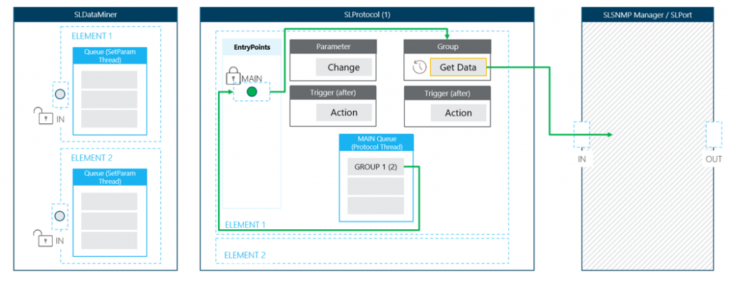
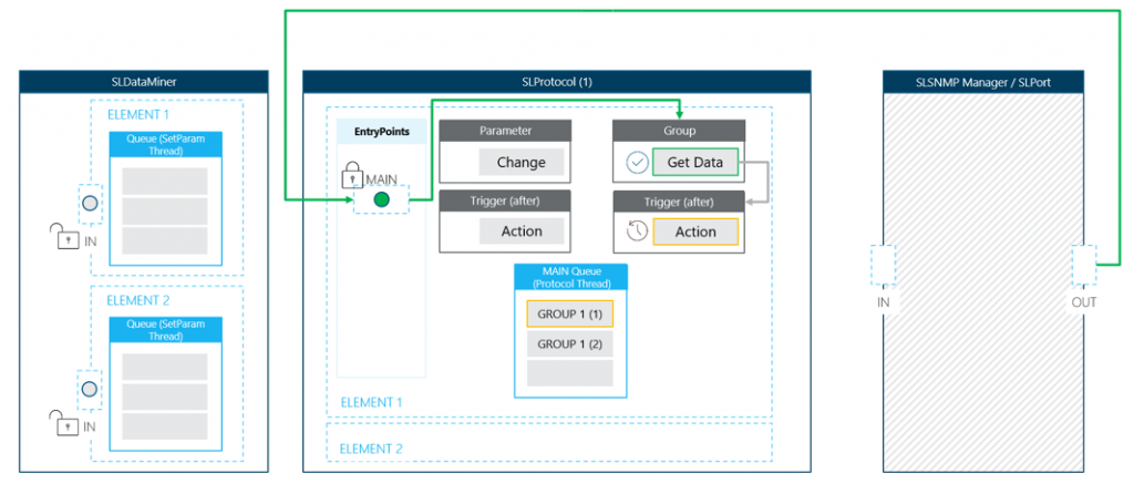
Step 4: Execution of the group
When all previous groups have been handled, it is time for the group to execute its content. For this use case, the group needs to retrieve data from a remote data source.
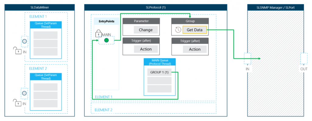
Once the request is in care of SLSNMP Manager or SLPort, the entry point will be unlocked, allowing others to interact with this element.
Note
The group will remain in the (group) queue of the protocol thread until it is fully processed (see step 6).
Step 5: Second SET while polling data
The second button click happens before the data source returns the requested data. The parameter SET will first be added to the SET queue. As the element entry point is open, it will be executed immediately in the same way as the first button SET. This will again result in a group being placed in the (group) queue of the protocol thread. Handling the requested data from the data source will need to wait until this SET flow is done.
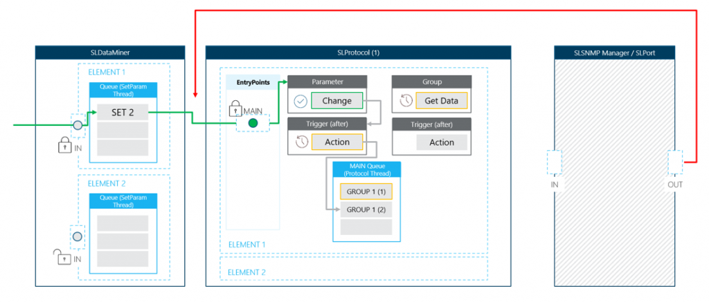
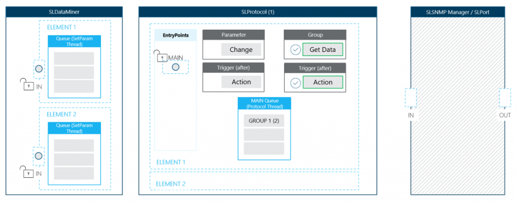
Step 6: Processing polled data
Once the group of the second button click is added to the (group) queue of the protocol thread, the returned data of the first group can be processed.
In this use case, a trigger needs to run after the group is finished. This could be used to perform any kind of action, for example formatting the received data. The group will remain in the queue until both the content and any linked logic is fully completed.
Imagine a cascade of logic after retrieving data:
Group > Trigger (after group) > Action (copy) > Trigger (on change) > Action ...
The group is only finished when each of these items is done. The longer the cascade, the slower the interaction. That is why a cascade of logic must be avoided. Instead use small actions and separate longer actions into multiple groups that are processed via the (group) queue of the protocol thread.
Step 7: Continue with next group
When the content and linked logic of the group of the first SET are done, the group is removed from the queue and the next one can be processed.
The same flow as described above will apply.