SCTE UPS
This connector can be used to monitor the state of a single power supply unit. It is used by DVE elements exported by the parent element SCTE UPS Collector.
About
The SCTE UPS connector uses SNMP to retrieve data from the device.
Product Info
| Range | Supported Firmware |
|---|---|
| 1.0.0.x | N/A |
| 1.0.1.x | N/A |
| 1.0.2.x | N/A |
Configuration
The element using this connector is automatically generated by the parent element SCTE UPS Collector.
How to use
In the sections below, you can find more information on the different data pages of the element and how you can use these.
General
This page displays general information about the UPS, such as the Name, Vendor, IP, and MAC, as illustrated in the example below.
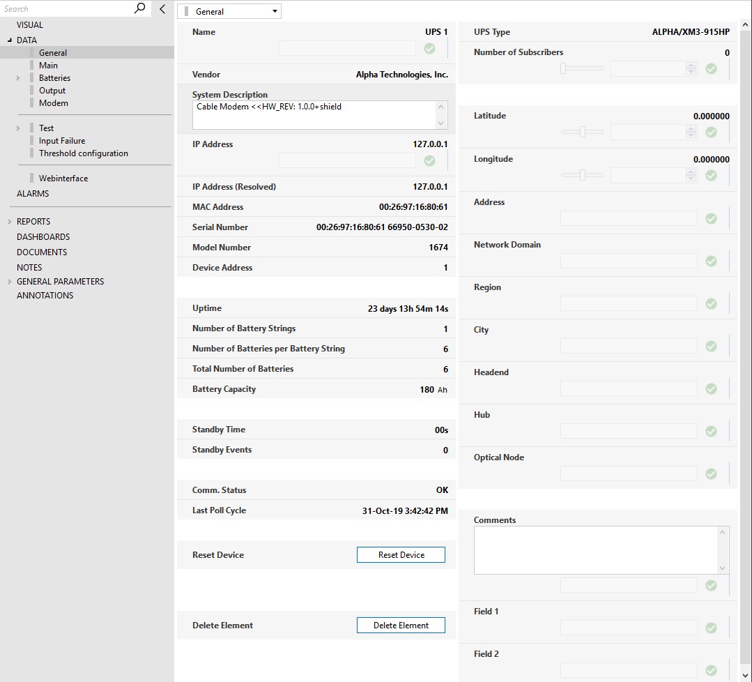
Some considerations regarding the parameters on this page:
IP Address: The value of this parameter can be either an FQDN hostname or an IP address.
IP Address (Resolved): This parameter can contain two types of values.
- If the IP Address parameter is an FQDN hostname, this parameter will contain the resolved IP address for that hostname.
- If the IP Address is a valid IP, this parameter will contain the same IP.
Standby Time: This is a theoretical value indicating how long the batteries will last before depletion when they are put to use. This depends on the proper configuration of the UPS parameters and on the Total Output Current parameter, which is only available when the inverter is off. At that moment, this value will be calculated.
Standby Events: Counts the number of events where the UPS reports that the Inverter Status is off.
Comm. Status: This parameter reports if the communication with the UPS is possible or if it has any errors. The possible values are OK, Error, and Timeout.
Reset Device: This button will physically reset the transponder of the device. Keep in mind that this process can take up to several minutes.
Delete Element: CAUTION! This button will erase the element from the DMA where it is located. This means that all history data for this element will be deleted as well.
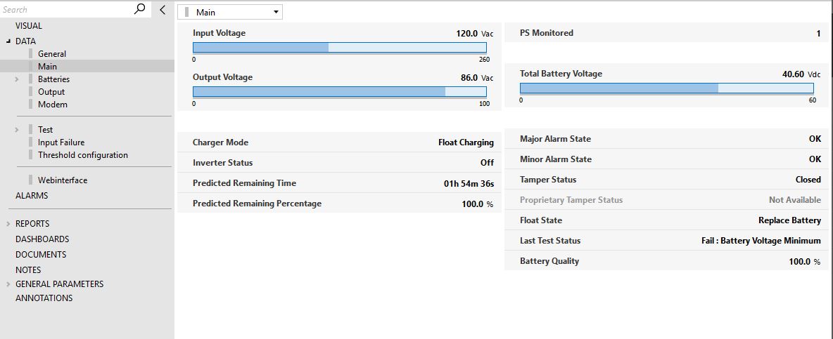
Main
This page displays relevant information regarding the UPS device, such as:
- Float State: This parameter indicates the health of the batteries. This is tested when the charger is in float mode.
- Predicted Remaining Time: This parameter displays a theoretical value indicating how long the batteries will last before depletion when they are put to use. This value depends on the Total Output Current.
- Battery Quality: This parameter indicates the health of the battery. It provides an indication of how the batteries will perform compared to their theoretical standby time.
The page also contains other parameters such as the Input Voltage, Output Voltage, and Alarms, as illustrated in the example below.
Batteries
This page displays all relevant information about the batteries of the UPS device, such as Voltages, Currents, Temperature, and Charger Mode.
This page also contains the Battery String Table and the Batteries Table, as illustrated below.
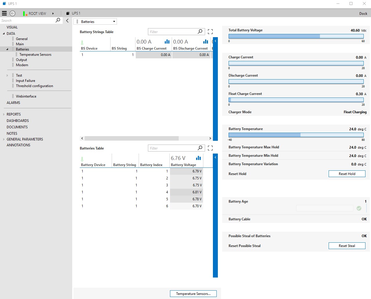
The Battery Age parameter needs to be properly configured by the operator, as it is one of the key parameters to calculate the Predicted Remaining Time.
A page button provides access to the Temperature Sensors subpage, where you can find the Temperature Sensor Table.
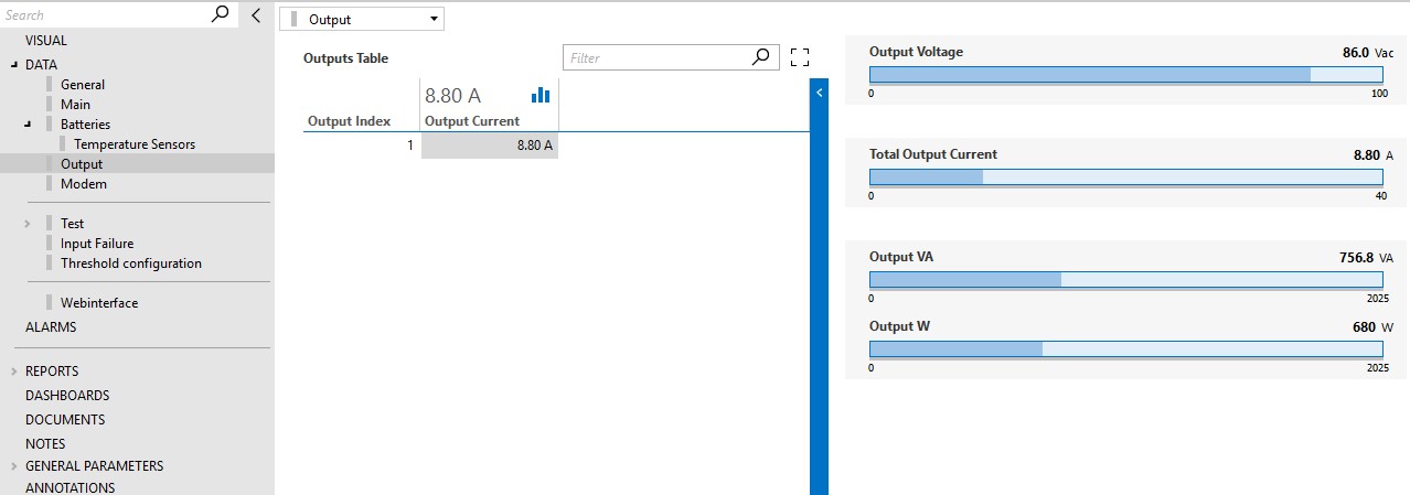
Output
This page displays relevant information regarding the output of the UPS device, such as the Output Current and the Output Voltage, as illustrated below.
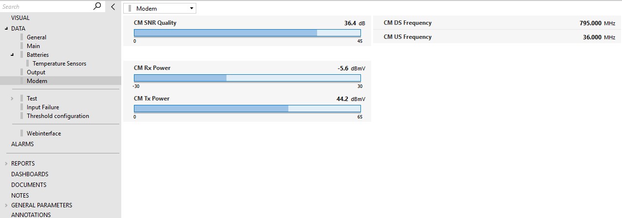
Modem
This page displays information about the modem transponder of the UPS device, such as the SNR Quality, and Rx and Tx Power.
Test
This page displays a summary of the last result of the tests performed by this connector. It contains parameters such as the Predicted Remaining Time, Battery Quality, Float State, and Battery Temperature Variation, as illustrated below.
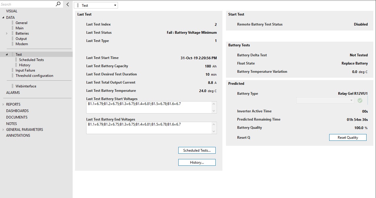
About the different kinds of tests:
Float State Test: The float state parameter is an indication for the health of the batteries and is tested when the charger is in float mode. The individual battery voltages cannot be under a certain threshold, which depends on the temperature while the charger is in float mode.
Possible values: Investigate Battery, Replace Battery, OK.
Formula:
IBthreshold = 13.2 + ( 25 - temperature ) * 0.0168
RBthreshold = 12.8 + ( 25 - temperature ) * 0.0168
Battery Delta Test: The individual battery voltages cannot exceed 0.5Vdc when the inverter is active because of a test. The individual battery voltages will only be checked when a test is running. Either the value "Not Tested" will be shown if no test has been performed yet, or the last value will be kept. Possible values: OK, Fail, Not Tested.
Battery Cable Test: This test is an indication of the status of the cable connected to the batteries. A problem with this cable might occur, resulting in invalid data retrieved from the device. This has an impact on the individual battery voltage. The value 0 Vdc will be retrieved while there is no problem with the batteries and the parameter that retrieves the number of batteries will show 0, which is invalid. The total battery voltage will still be retrieved correctly. We can conclude that there is a battery cable alarm when the number of batteries is 0, while the total battery voltage is larger than 0 Vdc.
Battery Temperature Holding/Variation Test: The temperature of the batteries is monitored, and the maximum and minimum value are stored in the parameters Batteries Temperature Max Hold and Batteries Temperature Min Hold, respectively. These parameters in turn are also monitored to calculate the Battery Temperature Variation, which is the difference between the Batteries Temperature Max Hold and Batteries Temperature Min Hold.
Via page buttons, you can also access the subpages Scheduled Tests and History.
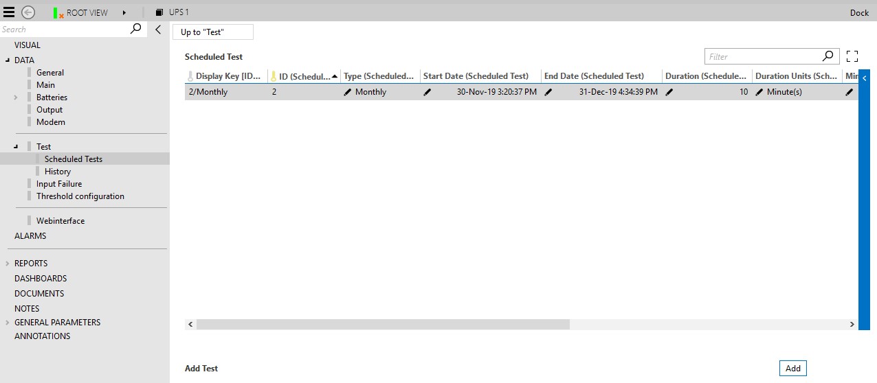
Scheduled Tests subpage (connector version < 1.0.2.21)
This subpage allows you to schedule tests to be performed on the UPS device.
To do so:
- At the bottom of the subpage, click the Add button. An entry will be created in the Scheduled Table.
- Define the Type of test: Yearly, Monthly or One Time. Default values will now be filled in for Start Time, Duration, Minimum Voltage Threshold, and Maximum Voltage Difference.
- Optionally, modify the default values for the other parameters of the entry. You can also define if the test should take the Minimum Voltage Threshold or the Full Drain Minimum Voltage Threshold into account. Only one of these can be used.
- Unless the test is to be executed One Time, define the End Date, which indicates until when the test will be valid.
- If you want to execute the scheduled test immediately, click the button Start Test in the row.
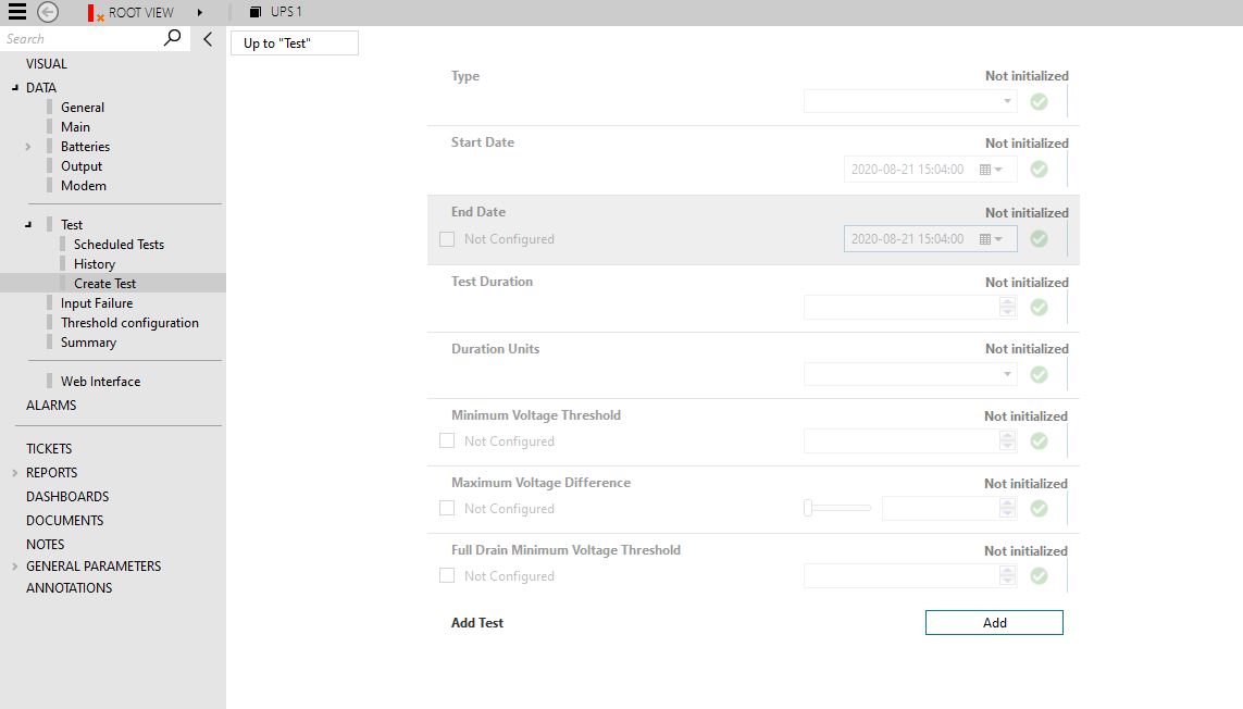
Create Test subpage (connector version >= 1.0.2.21)
From version 1.0.2.21 of the connector onwards, UPS tests are integrated in the DataMiner Scheduler module. To create a test, go to the Create Test subpage and follow the procedure below:
- Define the Type of test: Yearly, Monthly or One Time.
- Define the Start and End Date of the test. If the test is Yearly or Monthly, the End Date is mandatory. If the type is One Time, set the End Date to Not Configured.
- Set the Duration, Duration Unit, and Maximum Voltage Difference. You can also define if the test must take into account the Minimum Voltage Threshold or the Full Drain Minimum Voltage Threshold. These are mutually exclusive, so only one can be selected.
- Click the Add button. An entry will be created in the Scheduled Test table.
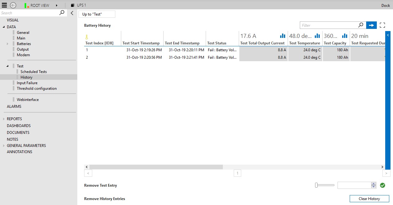
History subpage
The History subpage contains the Battery History table, which displays a summary of the results of the tests performed by this connector on the UPS device. Each entry in this table displays the Status of the test, the Total Output, the Temperature, and the Capacity.
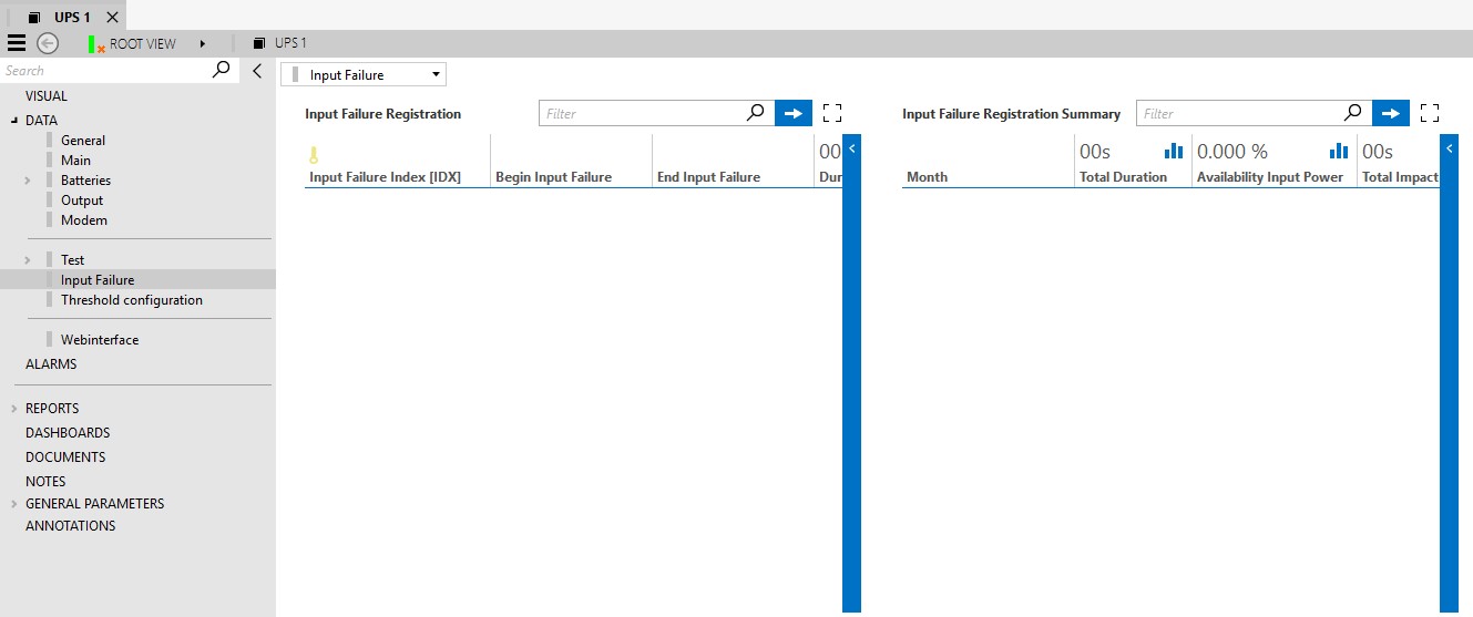
Input Failure
This page displays the tables Input Failure Registration and Input Failure Registration Summary, as illustrated below.
- The Input Failure Registration table keeps track of the input failure occurrences of the device. The table indicates when each failure started and ended, as well as the failure duration and impact on the network. A UPS device loses contact with the network when the batteries are fully depleted during an AC failure.
- The Input Failure Registration Summary table contains a monthly summary of the failures of the device. The values here are aggregated based on all the occurrences during the month.
Threshold Configuration
This page displays the Property Table, which contains the alarm threshold information for the parameters of the UPS device.
The alarm threshold data can be configured directly in the Property Table, or in bulk using the Export and Import functionality.
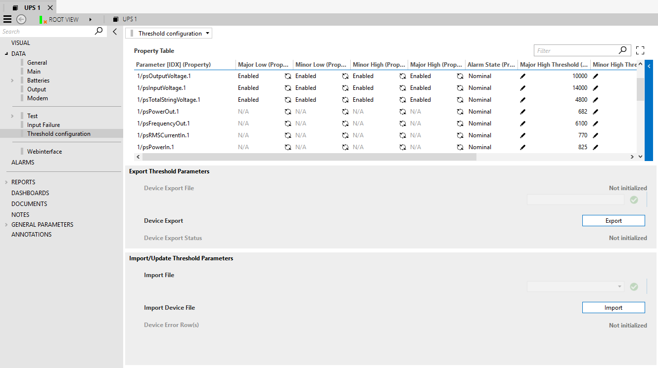
Exporting Threshold Parameters
To export the content of the Property Table:
In the Device Export File box, specify the name of the file to export.
Click the Export button.
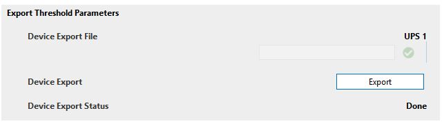
The connector will proceed to export an Excel file with the following prefix: "UPSElementNameDVE_"
Once the process is finished, the Device Export Status will change to Done.
The file will be placed in the following directory: C:\Skyline DataMiner\Documents\SCTE UPS Collector\Property
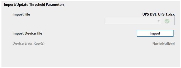
Import Threshold Parameters
To update the content of the Property Table in bulk:
Export the current Property Table, as explained in the previous section.
Go to the directory C:\Skyline DataMiner\Documents\SCTE UPS Collector\Property and open the exported file. The exported file will have the name of the collector element as a prefix.
Modify the Excel file and save it.
DO NOT MODIFY THE DEVICE ID, DEVICE NAME, INSTANCE OR PARAMETER.
Select the file in the Device Import File dropdown box and click the Import button.
The Import Progress bar will display the progress of the import, until it reaches 100. Once the import is done, you will also be able to see additional information, such as the number of Errors generated.
Web Interface
The web interface is only accessible when the client machine has network access to the physical element.