SCTE UPS Collector
With the SCTE UPS Collector connector, you can monitor a large number of UPS systems that are compatible with the SCTE-HMS MIB.
This connector uses SNMP to retrieve data from the device. Multiple UPS systems are polled at the same time, using the multithreading technology. For each UPS, a DVE is created, displaying the information of one single device.
About
Version Info
| Range | Key Features | Based on | System Impact |
|---|---|---|---|
| 1.0.0.x | Initial version | - | - |
| 1.0.1.x | Connector review | - | - |
| 1.0.2.x [SLC Main] | Scheduled test capabilities Property table Edit bulk Property table Support new battery models | - | - |
Product Info
| Range | Supported Firmware |
|---|---|
| 1.0.0.x | N/A |
| 1.0.1.x | N/A |
| 1.0.2.x | N/A |
System Info
| Range | DCF Integration | Cassandra Compliant | Linked Components | Exported Components |
|---|---|---|---|---|
| 1.0.0.x | No | Yes | - | SCTE UPS |
| 1.0.1.x | No | Yes | - | SCTE UPS |
| 1.0.2.x | No | Yes | - | SCTE UPS |
Configuration
Connections
SNMP Main Connection
This connector uses a Simple Network Management Protocol (SNMP) connection and requires the following input during element creation:
SNMP settings:
- IP address/host: This is a dummy address; the real polling IP is retrieved from the device table. You can fill in the following IP: 127.0.0.1.
- Port number: The port of the connected device, by default 161.
- Get community string: The community string in order to read from the device. The default value is public. All devices that are polled with this element must have this community string.
- Set community string: The community string in order to set to the device. The default value is private.
How to use
This connector will create a virtual element for each separate device. However, the main element must be used to manage the list of devices.
You can find more information about the data pages of the main element below.
Devices
The Devices page displays the Device Table, which lists all the UPS devices that are monitored by the SCTE UPS Collector element. This table displays relevant information about each UPS, such as the Total Battery Voltage, the Battery Temperature, and the Inverter Status. The Devices Table also allows you to configure general information of the devices, such as their Name, IP, and Battery Type. The connector will create a virtual element for each UPS available in this table.
This page also contains the parameter Number of Devices, which indicates how many UPS devices are currently monitored by the SCTE UPS Collector element.
Provisioning
On the Provisioning page, you can manage the list of UPS devices monitored by the collector. The page consists of several different sections, for which you can find more information below.
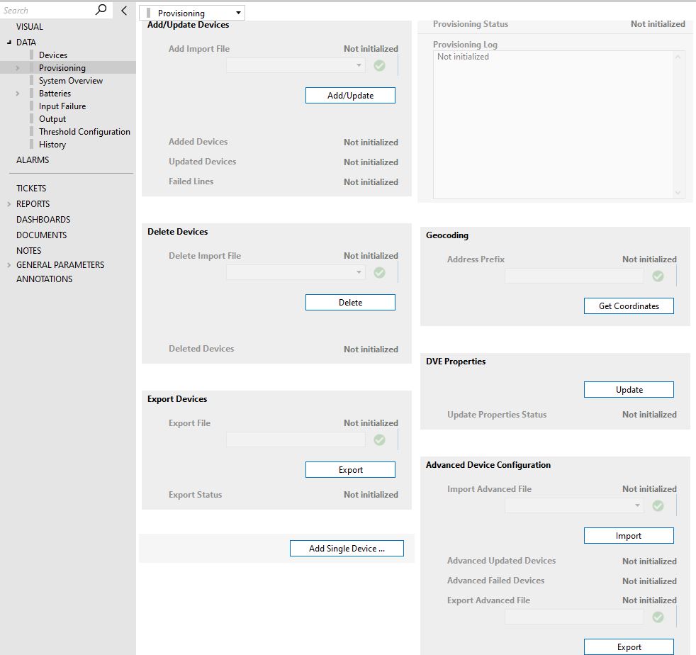
Add/Update Devices
This section allows you to add new UPS devices or update the current ones available in the Devices Table.
To add new devices, follow the steps below.
Step 1: Create a CSV file containing the general information of the devices. This file must contain the following columns in the same order as specified below:
- ID: Leave empty.
- Name: The name of the device; this will also be the name of the exported DVE element. Mandatory.
- IP Address: The IP address of the device. Mandatory.
- Read Community String: Optional.
- Write Community String: Optional.
- Latitude: Optional.
- Longitude: Optional.
- Address: Optional.
- Number of subscribers: Optional.
- Battery Type: The type of the battery must be supported by the SCTE UPS Collector. Mandatory.
- Battery Age: Optional.
- Network Domain: Optional.
- Region: Optional.
- City: Optional.
- Headend: Optional.
- Hub: Optional.
- Optical Node: Optional.
- Field 1: Optional.
- Field 2: Optional.
- Comments: Optional.
- View: Optional.
Step 2: Locate the provisioning file in the following directory: C:\Skyline DataMiner\Documents\SCTE UPS Collector\
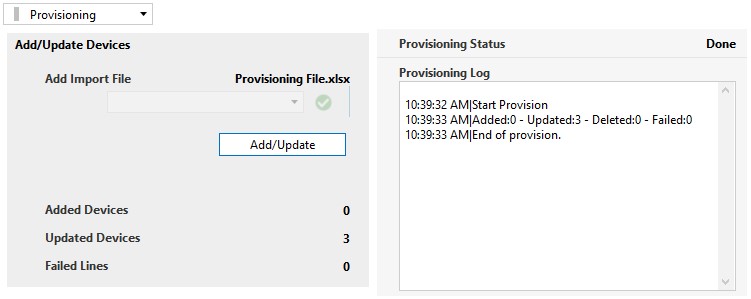
Step 3: Select the provisioning file in the Add Import File drop-down list and click the Add/Update button.
After this, the provisioning of the new devices will begin. You can view the progress and potential errors in the Provisioning Log.
When the process is finished, the number of Added Devices and Failed Lines will be displayed.
To update devices, follow the steps below.
Step 1: Export the currently available devices. See "Export Devices" below.
Step 2: Go to the directory C:\Skyline DataMiner\Documents\SCTE UPS Collector\ and open the exported file.
After this, you can modify the general information of the devices, such as the Name and the Battery Type. Save the changes.
Note
DO NOT MODIFY THE ID COLUMN.
Step 3: Select the new provisioning file in the Add Import File drop-down list and click the Add/Update button.
After this, the provisioning of the devices will begin. You can view the progress and potential errors in the Provisioning Log.
When the process is finished, the number of Updated Devices and Failed Lines will be displayed.
Delete Devices
To delete devices in bulk from the SCTE UPS Collector element, follow the steps below:
Step 1: Create a CSV file with the required provisioning format (See "Export Devices" below). Then put the names of the devices that are to be deleted in the Name column of the CSV file and save the changes.
Step 2: Place the CSV file in the following directory: C:\Skyline DataMiner\Documents\SCTE UPS Collector\
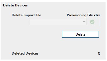
Step 3: Select the file in the Delete Import File drop-down list and click the Delete button.
After this, the deletion of the devices will begin. You can view the progress and potential errors in the Provisioning Log.
When the process is finished, the number of Deleted Devices will be displayed.
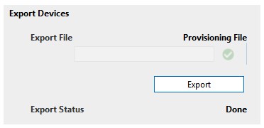
Export Devices
To export the UPS device information available in the Device Table to a CSV file, follow the steps below.
Step 1: In the Export File text box, write the name the export file should have.
Step 2: Click the Export button.
After this, the exporting of the devices will begin. When the process is finished, the Export Status will change to Done.
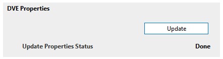
DVE Properties
To update the element properties of the DVEs created per UPS device, follow the steps below.
Step 1: Create the following element properties:
- Headend
- IP Address
- MAC
- Network Domain
- Place
- Region
Step 2: Click the Update button.
After this, the element properties of each DVE will be updated with the information of the corresponding UPS device.
When the process is finished, the Update Properties Status will change to Done.
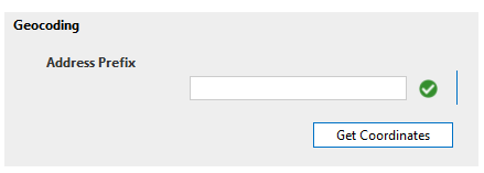
Geocoding
This function can be used to determine the latitude and longitude of the UPS devices based on their address, using a GOOGLE API.
Advanced Device Configuration
This feature allows you to configure the element description, alarm template and trend template of the UPS devices managed by the collector.
You can export the current configuration of the UPS devices by specifying the name of the file to export in the Export Advanced File field, and then clicking the Export button. The export file will be created in the following directory: C:\Skyline DataMiner\Documents\SCTE UPS Collector\Advanced Configuration
Modify this file and then upload it by selecting the file name in the Import Advanced File drop-down box and clicking the Import button.
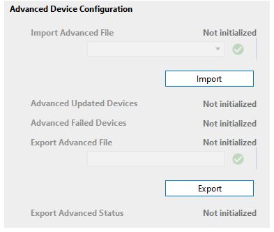
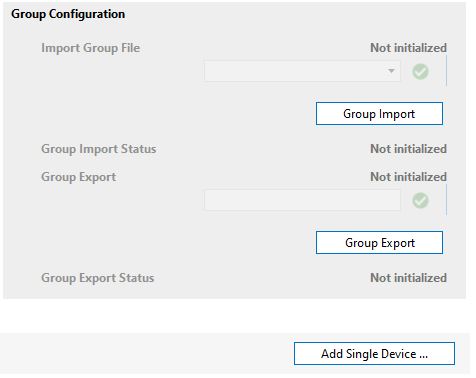
Group Configuration
This feature is available from version 1.0.2.21 of the connector onwards. It allows you assign a group to each UPS available in the collector. These groups are used by the SCTE UPS Manager to distribute the UPS Tests.
You can first export the CSV file in order to get the template with the list of the current UPS devices of the collector. After configuring the groups in the file, you can then import the CSV file to update the Custom Group Column in the Device table.
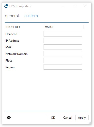
Add New Device
On the Provisioning page, the Add New Device page button opens a subpage where you can add a new UPS device to the collector element manually.
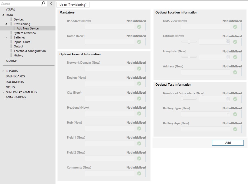
To add a new device, fill in the general information of the device. The IP Address and the Name of the UPS device must be filled in in order to create the device in the collector. The rest of the information is not mandatory.
Once the information is filled in, click the Add button.
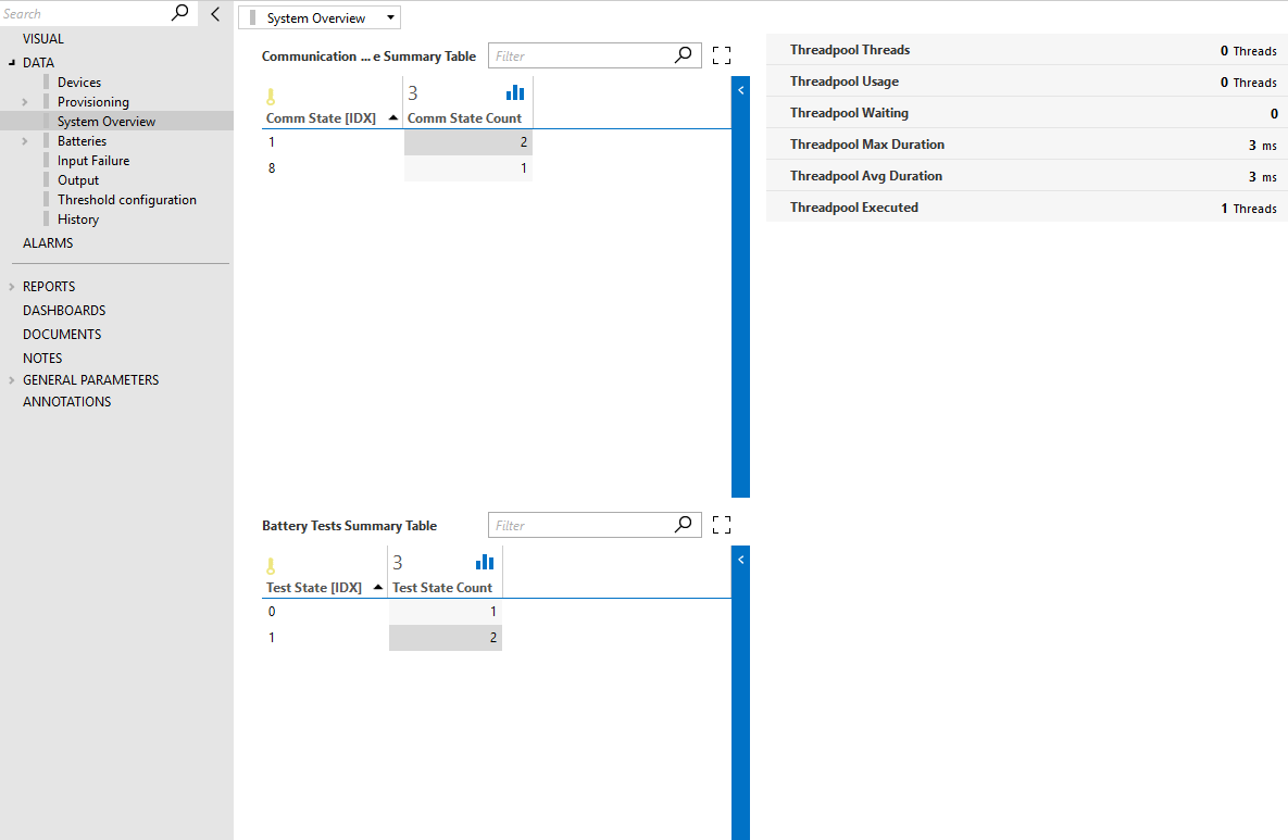
System Overview
This page contains general information about the devices polled by the SCTE UPS Collector element. This includes the Communication State Summary Table, which displays the number of UPS devices for each communication state, and the Battery Tests Summary Table, which shows the number of elements that are executing a battery test.
Finally, the page also includes the threadpool statistics of the collector, including the Threadpool Usage, Threadpool Max Duration, etc.
Multithread Logic
The multithreaded logic of the SCTE UPS Collector has the following default values:
- Thread pool size: 50 threads
- Time interval: 45 seconds
- Time: 1 second
In an ideal case, if a collector has for example 250 UPS devices, it will poll each UPS every time interval of 45 seconds. Therefore, in a maximum of 45 seconds, the connector should poll all 250 UPS devices. The time of 1 second indicates that the polling and thread usage will be done in chunks of 1 second. In other words, in the cycle of 45 seconds, every second about 6 UPS devices will be processed (250 UPSs /45 sec = 5.5 UPSs/sec) and therefore 6 threads will be used. Also, in every chunk of 1 second, the connector can use at most 50 threads (= thread pool size).
For this ideal scenario, the processing of each UPS would have to take less than 1 second, but this is not always the case. Suppose that a collector again has 250 UPS devices that need to be processed within 45 seconds, but this time it takes 2 seconds to process each UPS. The collector will need to use a thread pool of (250 UPSs/45s) * 2s/UPS = 11.11, so approximately 12 threads.
It is also important to consider that the time it takes to process a UPS (the thread duration) not only depends on the time it takes to poll and process information from a UPS, but also on the load of the system, e.g., how much CPU power is available.
By looking at the thread statistics on the System Overview page, you can check if the load on one collector is too large. For example, if Threadpool Usage has reached 50 threads (= the maximum threads allowed) and Threadpool Waiting constantly reaches high values, it is likely that the UPS devices are not being processed every 45 seconds. This could be an indication that the number of UPS devices for the collector needs to be reduced. In other words, there must be a balance between the duration of each thread (Threadpool Duration) and the number of UPS devices.
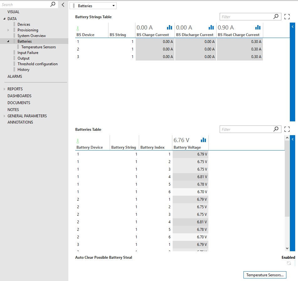
Batteries
The Batteries page displays the Battery String Table and the Batteries Table. These two tables contain relevant information regarding the batteries of all the UPS devices monitored by the collector.
The page also has a page button to the Temperature Sensors subpage, which contains the Temperature Sensor Table.
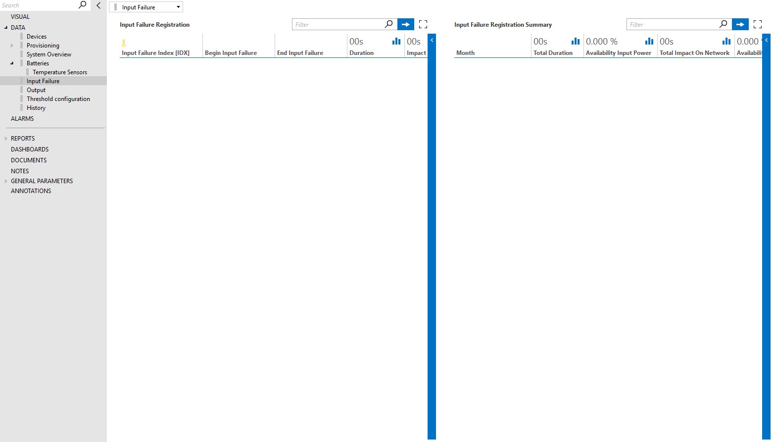
Input Failure
The Input Failure page displays the Input Failure Registration and Input Failure Registration Summary tables.
The Input Failure Registration table keeps track of input failure occurrences of all the devices. The table indicates when each failure started and ended, as well as the failure duration and impact on the network. A UPS device loses contact with the network when the batteries are fully depleted during an AC failure.
The Input Failure Registration Summary table contains a monthly summary of the failures of all the devices. This table displays the Total Duration of the Input Failure, the Failure Standby Events, the Impact on Network, and the Availability of Input Power and Network.
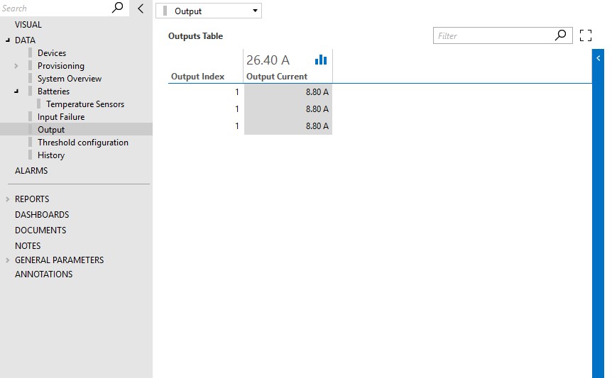
Output
The Output page contains the Output Table, which displays the power and current of all the UPS devices that are monitored by the collector.
Threshold Configuration
The Threshold Configuration page displays the Property Table, which contains the alarm threshold information for the parameters of the UPS devices monitored by the collector.
The alarm data can be configured directly in the Property Table or in bulk using the Export and Import functionality.
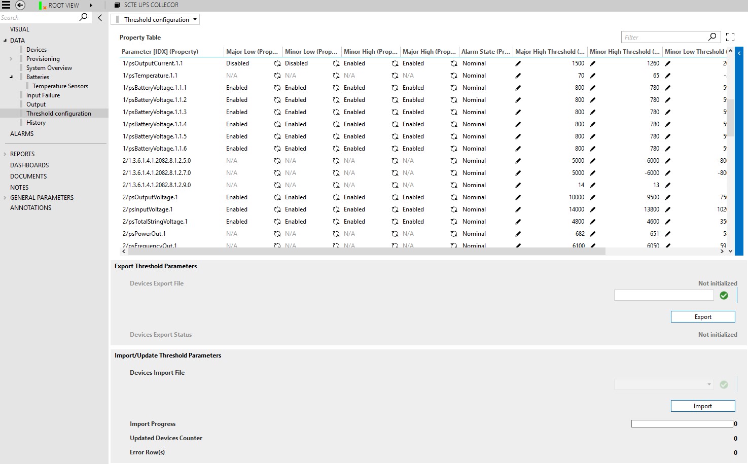
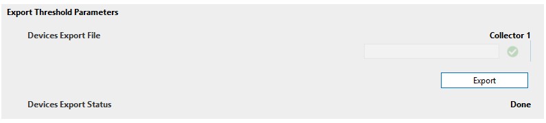
Export Threshold Parameters
To export the content of the Property Table, follow the steps below.
Step 1: In the Device Export File box, specify the name the export file should have.
Step 2: Click the Export button. An Excel file will be exported with the following prefix: "UPSElementName_"
Once the process is finished, the Device Export Status will change to Done. The file will be placed in the following directory: C:\Skyline DataMiner\Documents\SCTE UPS Collector\Property
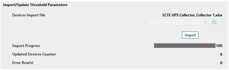
Import Threshold Parameters
To update the content of the Property Table in bulk, follow the steps below.
Step 1: Export the current Property Table (see "Export Threshold Parameters").
Step 2: Go to the following directory: C:\Skyline DataMiner\Documents\SCTE UPS Collector\Property.
In the directory, open the exported file (which will have the name of the collector element as a prefix), modify the file and save it.
DO NOT MODIFY THE DEVICE ID, DEVICE NAME, INSTANCE OR PARAMETER.
Step 3: Select the name of the file in the Device Import File drop-down list and click the Import button.
The Import Progress bar will display the progress of the import until it reaches 100. The number of Updated Devices and generated Errors will then also be displayed.
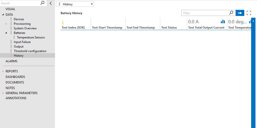
History
The History page contains the Battery History table, which contains a summary of the results of the tests performed by this connector. Each entry in this table displays the Status of the test, the Total Output, the Temperature, and the Capacity. The tests can be configured on the SCTE UPS DVE elements, which each represent a UPS device.