Manually provisioning endpoints and virtual signal groups for an IP Matrix element
In this tutorial, you will learn how to provision endpoints and virtual signal groups (VSGs) for an IP Matrix solution. These endpoints and VSGs will be used to visualize and manage the connections in the MediaOps Live solution.
The mentioned IP Matrix solution is a setup where a set of devices generate streams with a fixed multicast (TSoIP). These multicast IPs are then routed to a set of receivers by dynamically configuring the multicast IPs on the receivers.
graph LR
    subgraph Encoder x
    E1[Role: Source<br />Multicast: 239.1.x.1]
    end

    subgraph Decoder x
    D1[Role: Destination]
    end

    E1 -. TSoIP multicast .-> D1
Expected duration: 30 minutes
Tip
In this tutorial, the endpoints and virtual signal groups will be created manually using the Virtual Signal Groups app. Other ways to create endpoints and VSGs are through an automation script using the MediaOps Live API or by using the CSV import functionality.
Note
The content and screenshots of this tutorial were created using DataMiner 10.6.4 and MediaOps Live 1.0.0.
Prerequisites
A DataMiner System connected to dataminer.services, where MediaOps Live is installed.
Overview
- Step 1: Deploy the IP matrix elements
- Step 2: Create level and transport type
- Step 3: Create endpoints
- Step 4: Create virtual signal groups
Step 1: Deploy the IP matrix elements
This tutorial will make use of the Generic Dynamic Table connector to simulate the IP matrix functionality. To deploy this connector and create the necessary elements:
Look up the package Tutorial - SLC-AS-MediaOps.LIVE - IP Matrix in the Catalog.
Deploy the latest version of the package to your DataMiner Agent by clicking the Deploy button.
Tip
See also: Deploying a Catalog item to your system
This will automatically install the connector and create the following elements in your system:
Four elements representing encoders (sources):
- Name:
Encoder x(x: 1 ... 4). - Each element has one row (IP Out) with multicast IP 239.1.x.1.
- Name:
Four elements representing decoders (destinations):
- Name:
Decoder x(x: 1 ... 4). - Each element has one row (IP In). The multicast IP will be configured dynamically.
- Name:
Step 2: Create level and transport type
Next, you need to create a level and transport type in MediaOps Live. In this tutorial, the Video level and TSoIP transport type will be used. If these already exist in your system, you can skip this step.
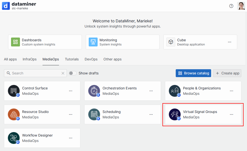
Open the Virtual Signal Groups app.
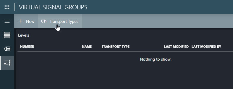
Go to the Levels page, and click the Transport Types button in the header bar.
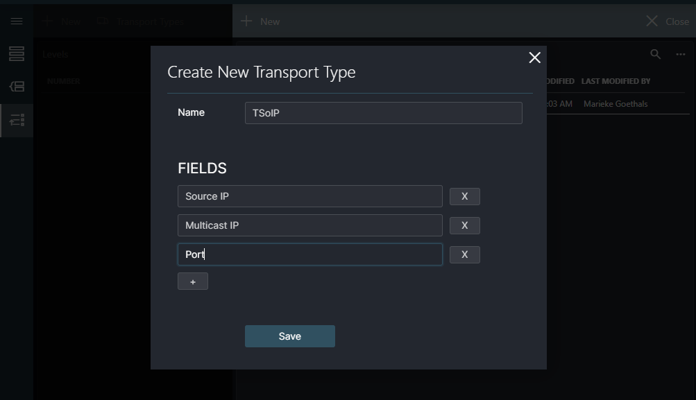
If the
TSoIPtransport type does not exist yet, create it by clicking the New button and specifying the following information:- Name:
TSoIP - Fields:
Source IP,Multicast IP, andPort
- Name:
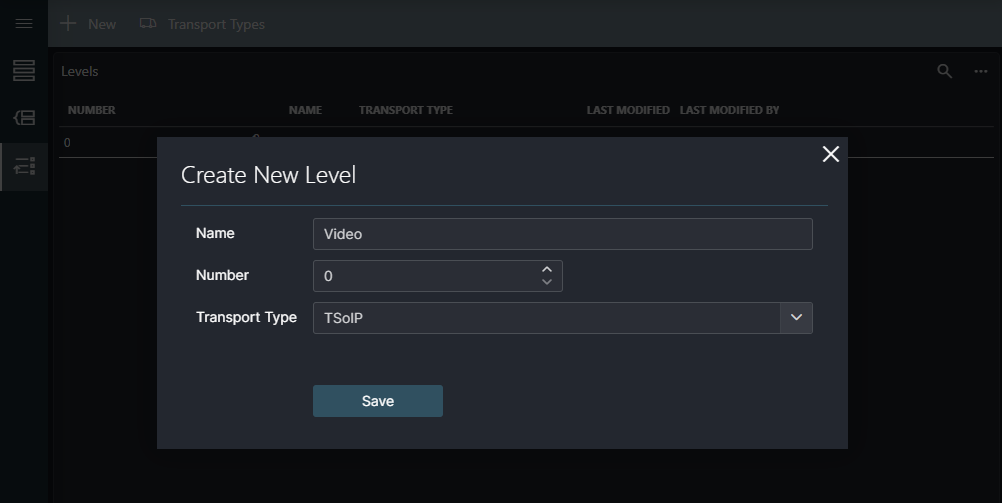
Back on the Levels page, if the
Videolevel does not exist yet, create it by clicking the New button and specifying the following information:- Name:
Video - Number:
0(or the next available number) - Transport Type:
TSoIP
- Name:
Step 3: Create endpoints
Next, you need to create endpoints for the inputs and outputs of the encoders and decoders. Each encoder element has one output (IP Out) that will be used as a source endpoint. The endpoint should contain the multicast IP address that is configured in the element. This multicast IP will be used later to configure the destination when creating a connection.
In the
Virtual Signal Groupsapp, go to the Endpoints page.Create a first endpoint for an encoder:
In the header bar, click New.
Fill in the following details in the pop-up window:
- Name:
Encoder 1(needs to be unique) - Role:
Source - Element: Select the
Encoder - 1element. - Identifier: Can be left empty as there is only one endpoint for this element.
- Control Element: Leave empty.
- Control Element Identifier: Leave empty.
- Transport Type:
TSoIP
As soon as you set the transport type to TSoIP, a new section will be displayed in the pop-up window where you can configure additional details.
- Name:
In the TSoIP section, fill in the multicast details:
- Source IP:
10.0.0.1(can be any valid IP address; not important for this tutorial) - Multicast IP:
239.1.1.1. This is the multicast IP configured in the element. The third octet should match the encoder number (1-4). - Port:
5000(can be any valid port, not important for this tutorial)
- Source IP:
Click Save to create the endpoint.
Repeat these steps to create endpoints for Encoder 2, Encoder 3, and Encoder 4.
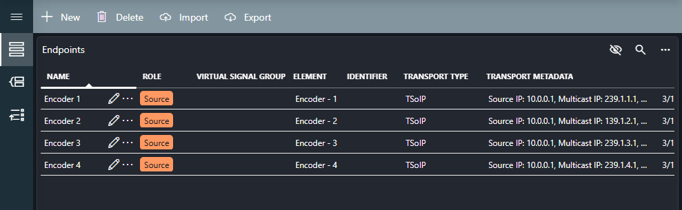
Now you should see that the source endpoints have been created linked to the correct elements.
Create a first endpoint for a decoder:
In the header bar, click New.
Fill in the following details in the pop-up window:
- Name:
Decoder 1(needs to be unique) - Role:
Destination - Element: Select the
Decoder 1element from the dropdown - Identifier: Can be left empty as there is only one endpoint for this element.
- Control Element: Leave empty.
- Control Element Identifier: Leave empty.
- Transport Type:
TSoIP
This time you do not need to provide details for the TSoIP section because this is a destination endpoint.
- Name:
Click Save to create the endpoint.
Repeat these steps to create endpoints for Decoder 2, Decoder 3, and Decoder 4.
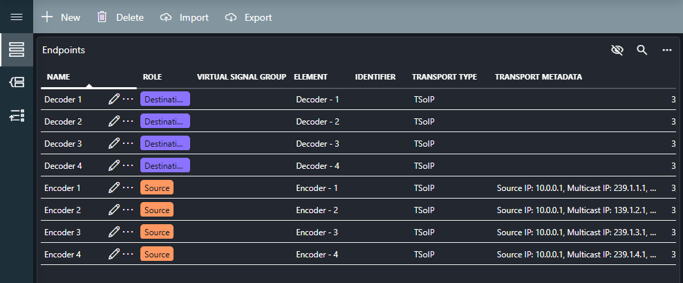
Now you should see that the destination endpoints have been created linked to the correct elements.
Step 4: Create virtual signal groups
Next, virtual signal groups (VSGs) need to be created. These are logical groupings that allow the creation of connections between multiple endpoints at the same time. In this case, a VSG must be created for each endpoint created in the previous step. The endpoints will be assigned to the VSG on the Video level, but you can adjust this based on your needs.
In the Virtual Signal Groups app, go to the Virtual Signal Groups page.
In the header bar, click the New button to create a new VSG.
Fill in the following details in the pop-up window, and then click Save:
- Name:
Encoder 1(needs to be unique) - Description: A meaningful description (optional).
- Role:
Source
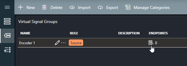
In the table, a record will be added for the VSG.
- Name:
Assign an endpoint to the VSG:
Click the edit endpoints icon in the row of the VSG you have just created.
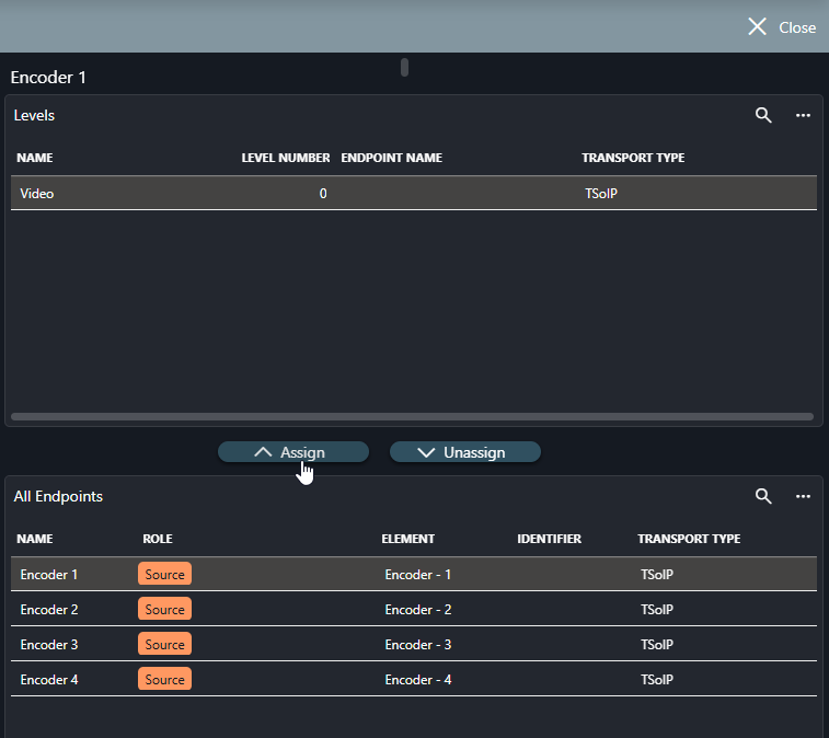
A side panel will open.
In the table at the top, select the Video level.
In the table at the bottom, select the endpoint you created in the previous step (e.g., Encoder 1).
Click Assign to assign the endpoint to the VSG.
The endpoint will now be assigned on the Video level.
Repeat these steps to create more VSGs for inputs and outputs as needed, using the role Source for the encoders and the role Destination for the decoders.
Up next
Now that you have created endpoints and virtual signal groups for an IP matrix solution, you can create a connection handler script by following the tutorial Creating a connection handler script for an IP Matrix element. Once that is done, you will be able to create connections between the encoders and decoders using the Control Surface app.