Getting started with alarm templates
This tutorial explains how to get started with alarm templates.
Expected duration: 15 minutes
Note
The content and images for this tutorial have been created using DataMiner version 10.4.6.
Tip
See also: Kata #33: Master alarm templates on DataMiner Dojo 
Prerequisites
A DataMiner System that is connected to dataminer.services.
Tip
A new DataMiner as a Service system comes with a dataminer.services connection out of the box, so it automatically meets this requirement.
Overview
- Step 1: Deploy the simulation element
- Step 2: Configure alarm monitoring using normal thresholds
- Step 3: Configure hysteresis
- Step 4: Configure alarm monitoring using rate thresholds
- Step 5: Configure alarm monitoring using relative thresholds
- Step 6: Configure alarm monitoring using absolute thresholds
- Step 7: Define a condition to disable alarm monitoring
Step 1: Deploy the simulation element
For this tutorial, a simulation protocol is available that allows you to simulate some practical use cases. In this first step, you will deploy this protocol and then create an element using the protocol.
Look up the Generic Data Simulator in the Catalog.
Deploy the protocol to your DataMiner Agent by clicking the Deploy button.
Tip
See also: Deploying a Catalog item to your system
In DataMiner Cube, go to Apps > Protocols & Templates and verify whether the protocol is available.
In the Versions column, right-click the deployed version of the protocol and select Set as production.
Creating the alarm template for the production version will have the advantage that there will be no need to create a new alarm template for every new version of the protocol. Even when a new version is set as production, the same alarm template will continue to apply.
Make sure the Production version is selected, right-click the Elements column on the right, and select New element.
Create a new element with a name of your choice.
The production version of the Generic Data Simulator protocol should automatically be selected in the element editor.
Tip
See also: Adding elements
Step 2: Configure alarm monitoring using normal thresholds
Look up the newly created element in the Cube Surveyor.
Right-click the element and select Protocols & Templates > Assign alarm template > <New alarm template>.
In the dialog, keep the Alarm template option selected, specify the name Default, and click OK.
Select the CPU parameter, and click OK at the bottom of the window.
In the element, you should now see the alarm severity color displayed next to the CPU parameter on the General page.
Set Simulation Mode to a different value and check what happens.
The different modes simulate situations that can trigger alarms, so the alarm severity color next to CPU will change accordingly, and an alarm may be generated in the Alarm Console.
Step 3: Configure hysteresis
When Simulation Mode is set to Spikes, alarms will exist for short periods of time, which might make it difficult for operators to notice the alarms. The alarms might also not be relevant, as it could be that operators are only interested if the threshold is violated for longer periods of time. To deal with this, you can configure the hysteresis feature in the alarm template.
Right-click the element in the Surveyor, and select Protocols & Templates > View alarm template 'Default'.
This will open the alarm template again.
In the HYST ON column for the CPU parameter, specify 10.
An alarm will now only be generated if the CPU value remains high for 10 seconds.
In the HYST OFF column for the CPU parameter, specify 20.
The alarm will now remain present for 20 seconds longer after the CPU value drops below the alarm threshold, ensuring that operators have more time to notice it.
Click OK to save your changes.
Step 4: Configure alarm monitoring using rate thresholds
If a parameter is a counter that continuously increases (e.g. received packets on a network interface), it is not possible to define regular alarm thresholds. For such a parameter, you can use rate thresholds instead.
Right-click the element in the Surveyor, and select Protocols & Templates > View alarm template 'Default'.
At the top of the template, click Only monitored parameters and select Only protocol parameters instead.
All the parameters included in the protocol will now be displayed.
Select the Counter Parameter.
In the Type box, select Rate.
In the CRIT HI column, specify 3.
With this configuration, when the current value of the parameter will increase by 3 or more compared to the previously measured value, a critical alarm will be triggered.
Click OK to save your changes.
Counter Parameter will now also be monitored.
Set Simulation Mode to High Load.
The parameter value will now increase by 5 on every update, so a critical alarm will be triggered.
Set Simulation Mode back to Low Load.
The alarm will be cleared again, as the parameter value will now increase by 1 on every update.
Step 5: Configure alarm monitoring using relative thresholds
With relative alarm thresholds, you can define a baseline from which the value can deviate percentage-wise. This can especially be useful for tables where every row can have a different baseline value.
Right-click the element in the Surveyor, and select Protocols & Templates > View alarm template 'Default'.
At the top of the template, click Only monitored parameters and select Only protocol parameters instead.
Select the Interfaces: Bitrate parameter.
In the Type box, select Relative.
In the CRIT LO and CRIT HI column, specify 20.
With this configuration, if the parameter decreases or increases by 20% compared to the baseline value, an alarm will be triggered.
In the NORMAL column, click [Baseline].
Right-click each cell in the Current value column, and select Use current value as baseline value.
The value that are currently in the table will now be considered the normal values to compare against.
Note
With the Automatically update the baselines option at the bottom, the baseline values can be updated automatically based on the parameter history. However, you can only use this option if trending has been enabled on the parameter for at least the number of days mentioned in the Trend window box.
Click Close and then OK to save the changes.
Go to the Interfaces data page of the simulation element.
You will see that the Bitrate column of the Interfaces table is colored according to the current alarm severity.
Change the values in the Bitrate Baseline and Bitrate Variance columns to simulate alarms.
Keep in mind that changing the Bitrate Baseline value will only change the behavior of the simulation. This will not change the baseline value of the alarm template.
Step 6: Configure alarm monitoring using absolute thresholds
In some cases, it can be easier to define in absolute numbers how much a value can deviate from the baseline (e.g. when the baseline is close to zero).
Right-click the element in the Surveyor, and select Protocols & Templates > View alarm template 'Default'.
Hover the mouse pointer over the Interfaces:Bitrate parameter, and click the + icon to duplicate the parameter.
In the filter box of the first instance of the duplicated parameter, specify the filter rule Ethernet1/1.
Important
When you duplicate parameters in an alarm template and apply different monitoring based on filters, make sure that the most strict rule is always at the top, because the first rule for which a match is found will be used, and the rules below it will no longer be checked.
In the Type box, select Absolute.
In the CRIT LO and CRIT HI column, specify 0.5.
In the NORMAL column of the row with the Ethernet1/1 filter, click [Baseline].
In the Baseline value column for Ethernet1/1, set the value to 0.
Click Close and then OK to save the changes.
In the Interfaces table of the simulation element, set the Bitrate Baseline value for Ethernet1/1 to 0, to simulate a bitrate fluctuating around 0.

Step 7: Define a condition to disable alarm monitoring
By defining alarm conditions, you can dynamically enable and disable alarm monitoring based on other values.
Right-click the element in the Surveyor, and select Protocols & Templates > View alarm template 'Default'.
In the CONDITION column for the first Bitrate parameter instance, select <New>.
Configure the condition as illustrated below, and click OK:
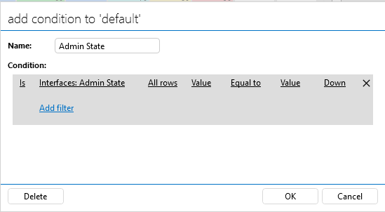
Select the same condition for the other Bitrate parameter instance.
Click OK to save your changes.
In the Interfaces table of the simulation element, switch the Admin State for some interfaces to Down.
The alarm severity color should no longer be displayed for those interfaces.
